Passive control type wind power generation system capable of automatically tracking maximum wind energy

A technology for wind power generation systems and maximum wind energy, applied in control systems, control generators, collectors, etc., can solve the problems of not taking into account the maximum wind energy capture at the same time, low technical difficulty, simple control, etc., to achieve simple structure, high efficiency, The effect of strong overload capacity

Inactive Publication Date: 2009-03-04
HARBIN INST OF TECH
View PDF0 Cites 7 Cited by
  • Summary
  • Abstract
  • Description
  • Claims
  • Application Information

AI Technical Summary

Problems solved by technology

[0005] The purpose of the present invention is to solve the main problem existing in the current off-grid wind power generation system, which is that the maximum wind energy capture cannot be taken into account at the same time, and the maximum power control and the advantages of simple control, small technical difficulty, low cost and high reliability can be realized. Provide a A passive control type maximum wind energy automatic tracking wind power generation system

Method used


Image

  • Passive control type wind power generation system capable of automatically tracking maximum wind energy
  • Passive control type wind power generation system capable of automatically tracking maximum wind energy
  • Passive control type wind power generation system capable of automatically tracking maximum wind energy

Examples


specific Embodiment approach 1

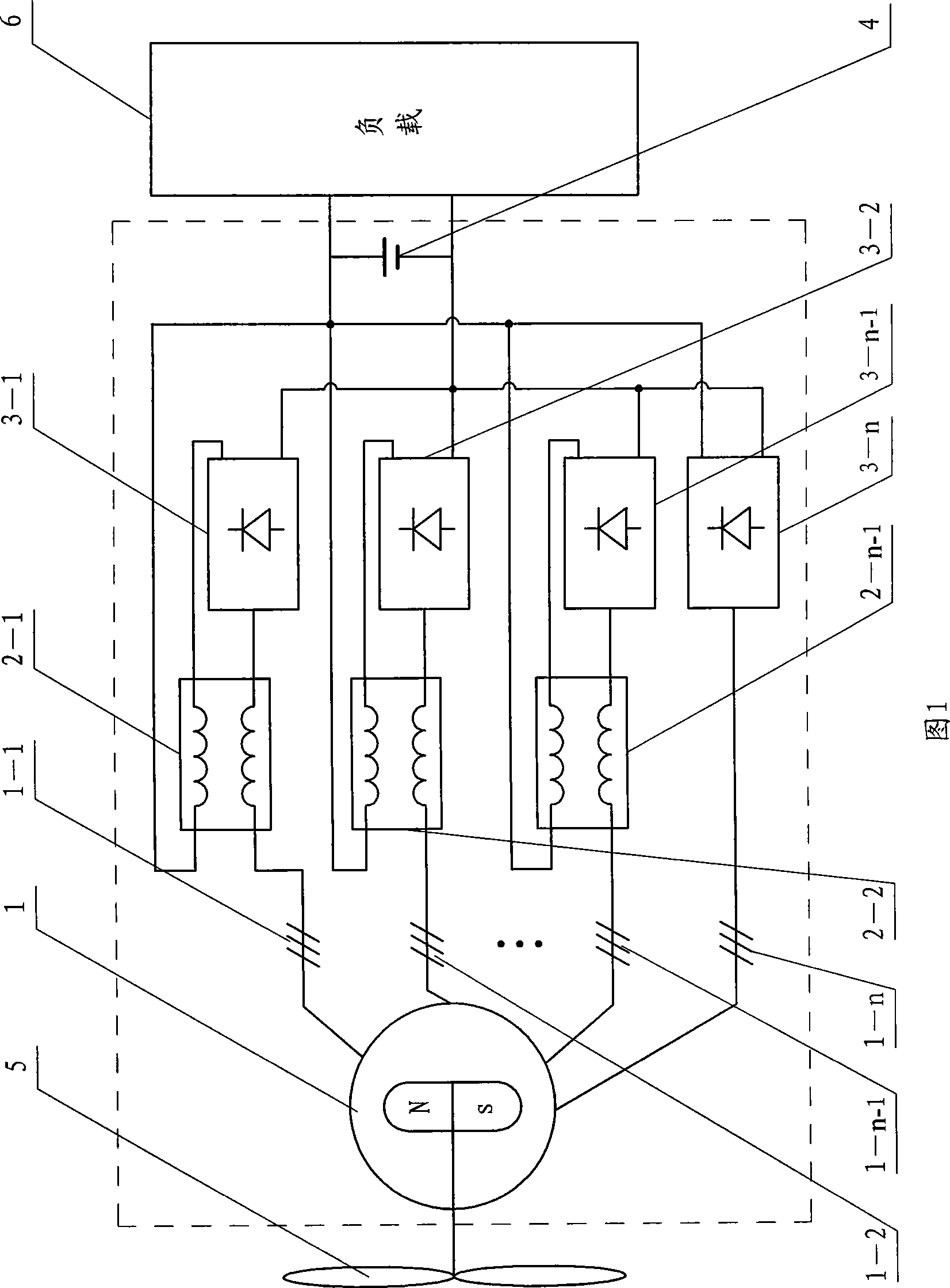
[0014] Specific Embodiment 1: The present embodiment will be described below in conjunction with FIG. 1. This embodiment includes a permanent magnet generator 1, n-1 reactors (2-1, 2-2...2-n-1), and n rectifiers (3-1, 3-2...3-n-1 and 3-n) and DC power supply 4, permanent magnet generator 1 has n sets of windings (1-1, 1-2...1-n-1 and 1—n),

[0015] The first winding 1-1 is connected to one end of the AC winding of the first reactor 2-1, and the other end of the AC winding of the first reactor 2-1 is connected to the input end of the first rectifier 3-1, and the first rectifier 3 The positive output end of -1 is connected to one end of the DC winding of the first reactor 2-1, the other end of the DC winding of the first reactor 2-1 is connected to the positive pole of the DC power supply 4, and the negative pole of the first rectifier 3-1 The output terminal is connected with the negative pole of the DC power supply 4,

[0016] The second winding 1-2 is connected to one end o...

specific Embodiment approach 2

[0021] Specific implementation mode two: the following combination Figure 4 and Figure 5 This embodiment is described. The difference between this embodiment and Embodiment 1 is that the impedance values ​​of the first reactor 2-1 to the n-1th reactor 2-n-1 decrease by 20% to 80% sequentially, and other components and The connection mode is the same as that in Embodiment 1.

[0022] n reactors (2-1, 2-2...2-n) are adjustable reactors, such as Figure 4 As shown, the core of the reactor is in the shape of "Tian", and the core columns on both sides of each reactor are wound with DC windings Nc1, Nc2, Nc3 and Nc4, and the coils of Nc1 and Nc2 are wound on one side of the core column. On the contrary, the coils of Nc3 and Nc4 wound on the other side of the stem are opposite to each other, and the two output terminals of Nc1, Nc2, Nc3 and Nc4 connected in series are respectively connected to a corresponding rectifier (3-1, 3-2 ...or 3—n) positive output end and load 6 positive...

specific Embodiment approach 3

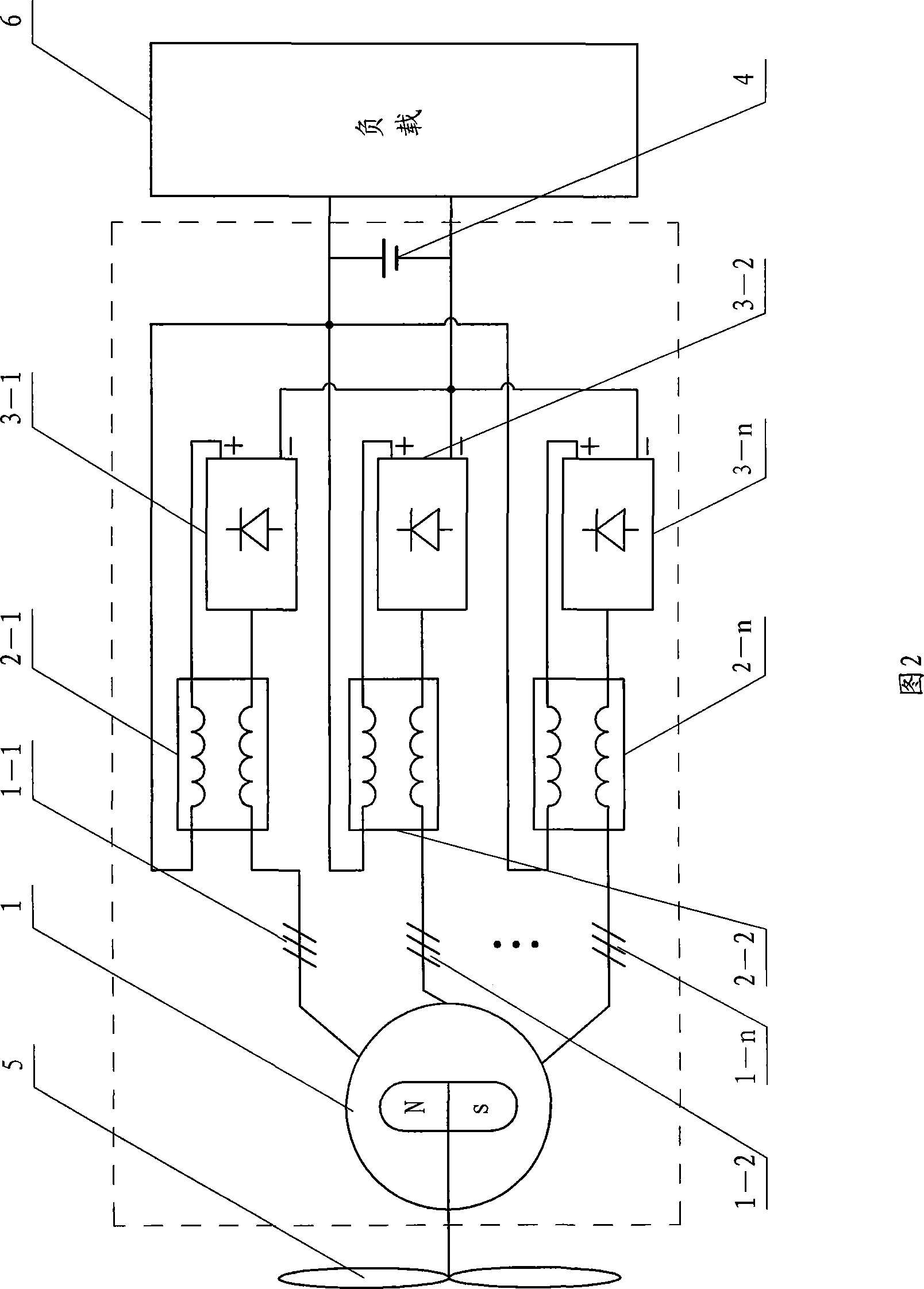
[0026] Specific embodiment three: below in conjunction with Fig. 2, Image 6 Describe this embodiment, the difference between this embodiment and Embodiment 1 is that it also includes the nth reactor 2-n,

[0027] The n-th winding 1-n is connected to one end of the AC winding of the n-th reactor 2-n, and the other end of the AC winding of the n-th reactor 2-n is connected to the input end of the n-th rectifier 3-n, and the n-th rectifier 3 The positive output end of —n is connected to one end of the DC winding of the nth reactor 2—n, the other end of the DC winding of the nth reactor 2—n is connected to the positive pole of the DC power supply 4, and the negative pole of the nth rectifier 3—n The output end is connected with the negative pole of the DC power supply 4 . Other composition and connection methods are the same as those in Embodiment 1.

[0028] like Image 6Shown is the output characteristic of the power generation system, and the curve L-out is the ideal state ...


PUM


Abstract

A passive control-typed maximum wind energy automatic tracking wind power generating system belongs to the field of motors. The object of the invention is to solve the main problems existing in the out-of-grid type wind power generating system that the maximum wind capture, the maximum power control and the advantages of simple control, small technical difficulty, low cost and high reliability can not be realized simultaneously. The wind power generating system comprises a permanent magnet generator, n-1 reactors, n rectifiers and a DC power, wherein, the permanent magnet generator is provided with n sets of winding; the first n-1 sets of winding are respectively connected with the AC winding of the n-1 reactors in series, and then respectively and correspondingly connected with the n-1 rectifiers; the nth set of winding is directly connected with the nth rectifier; the DC winding of the n-1 reactors are respectively connected at the anode output terminal of the first n-1 rectifiers in series; and the n rectifiers are connected at the two ends of DC power after connecting in parallel. The wind power generating system has simple structure, low cost, high efficiency, strong overload capacity and high reliability, and can achieve the maximum wind energy automatic tracking control of the wind power generating system.

Description

technical field [0001] The invention relates to a passive control type maximum wind energy automatic tracking wind power generation system, which belongs to the field of motors. Background technique [0002] In a wind power generation system, the output voltage of a wind generator (especially a permanent magnet generator) fluctuates in a wide range due to a wide range of wind speed. Therefore, off-grid generators often cannot be directly connected to the load, but charge the battery through a rectifier, store the electric energy, and supply power to the load through the battery; it is also possible to use a controllable rectifier regulator to enable the generator to simultaneously supply power to the load. and battery power. The basic block diagrams of these two systems are shown in Figure 3-1 and Figure 3-2 shown. However, since the generator adopts a single winding in this system, the output power of the generator is much smaller than that of the wind turbine, and the...

Claims


Application Information

Patent Timeline
Patent Type & Authority Applications(China)
IPC IPC(8): H02J7/14H02P9/00H02K21/48
Inventor 寇宝泉吴红星李立毅
Owner HARBIN INST OF TECH
Why Eureka
Try Eureka