Tube stamping engraving die

A technology of fonts and tubes, applied in stamping, decorative art, printing, etc., can solve problems such as poor lettering effect, lower lettering efficiency, and difficulty in demoulding, and achieve the effects of easy extraction, improved lettering efficiency, and good lettering effect

Inactive Publication Date: 2009-03-11
SUZHOU ERMA MECHNICAL & ELECTRICAL
View PDF0 Cites 7 Cited by
  • Summary
  • Abstract
  • Description
  • Claims
  • Application Information

AI Technical Summary

Problems solved by technology

[0003] However, the above-mentioned mold has the following defects: in order to prevent the pipe from moving during stamping, resulting in poor lettering effect, the pipe must be tightened on the lower module, but once the tension is tight, it often results in the process of unloading the pipe from the lower module after the lettering is completed. That is to say, "demoulding" becomes extremely difficult, which not only takes time and effort, but also greatly reduces the efficiency of lettering

Method used


Image

  • Tube stamping engraving die
  • Tube stamping engraving die
  • Tube stamping engraving die

Examples


Embodiment 1

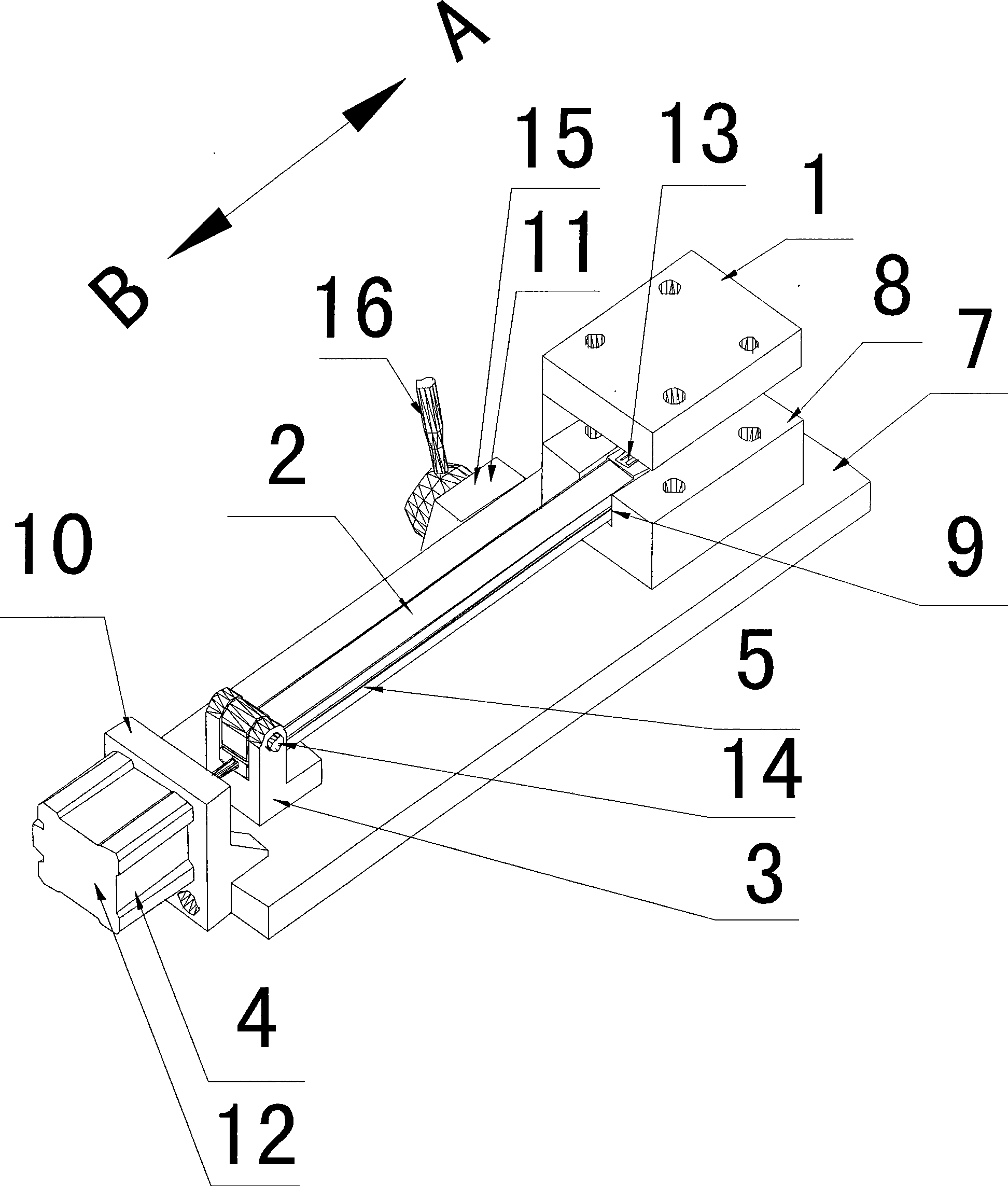
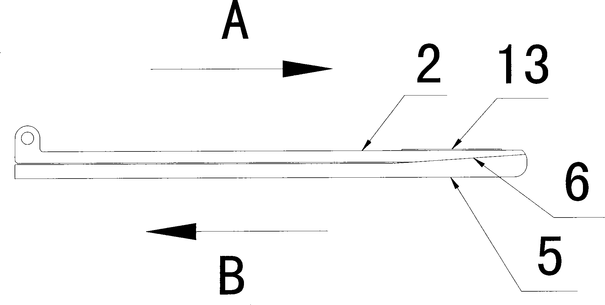
[0028] Example 1: Combining figure 1 , figure 2 Shown is a specific embodiment of the pipe stamping lettering die device of the present invention, which consists of an upper module 1, a lower module 2, a bracket 3, a power mechanism 4, a core block 5, a bottom plate 7, a lower module seat 8, and a mounting seat 10 and control device 11 constitute.

[0029] The upper module 1 is engraved with concave characters ( figure 1 Invisible due to the view), and the lower module 2 is engraved with a convex font 13 matching the concave font.

[0030] The bracket 3 is fixed on the bottom plate 7 , and one end of the lower module 2 is pinned to the bracket 3 , so that it can swing up and down around the pin shaft 14 .

[0031] The core pulling block 5 is located below the lower module 2 , and one end thereof is connected to the power mechanism 4 . In this embodiment, the power mechanism 4 is a cylinder 12 , and the corresponding control device 11 is a cylinder valve 15 . The cylinder ...

Embodiment 2

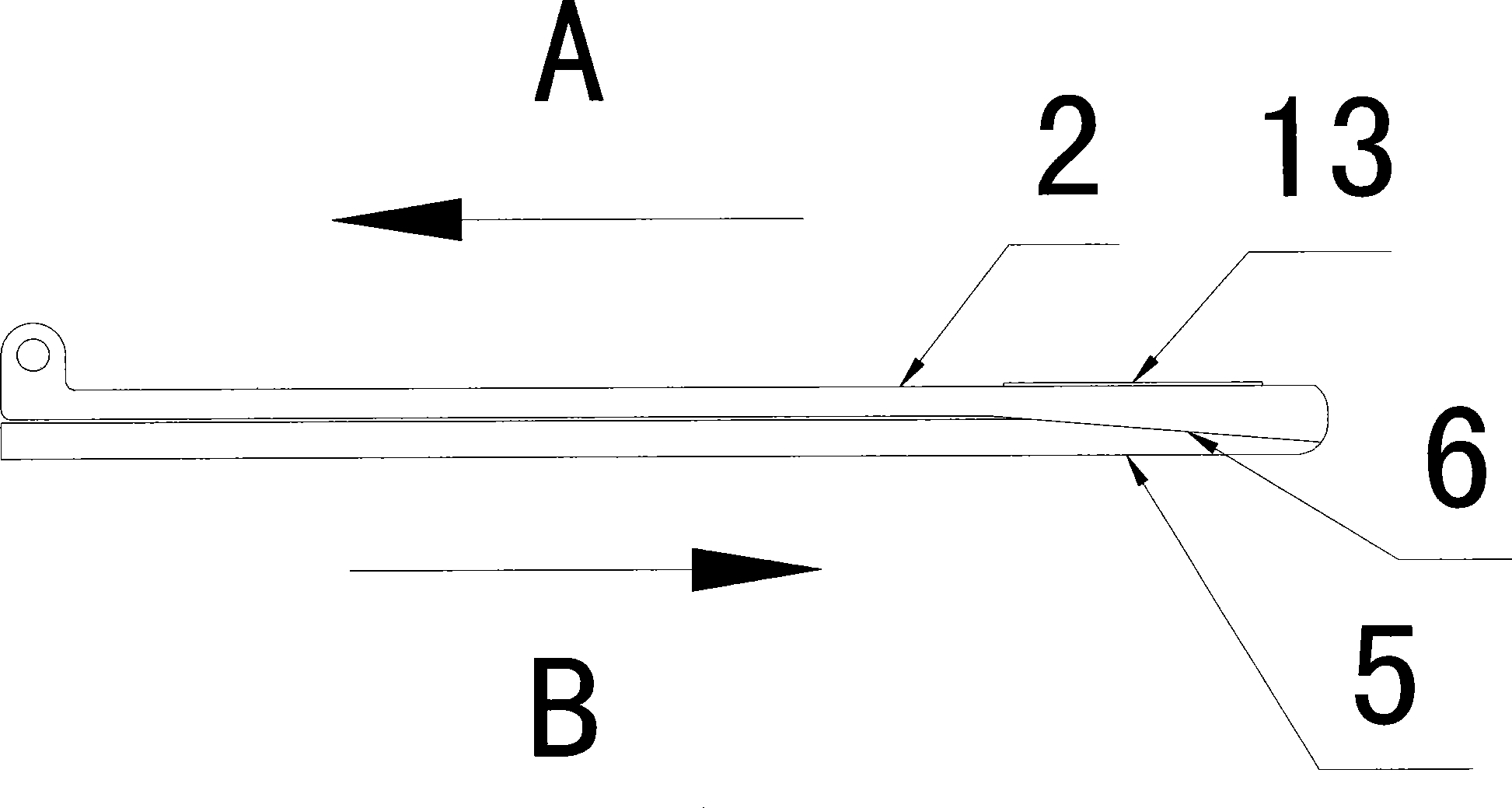
[0042] Example 2: Combining figure 1 and image 3 Shown is another specific embodiment of the tubular stamping lettering die device of the present invention. The structure of this embodiment is basically the same as that of Embodiment 1 and will not be described again. The only difference is that the upper part of the core pulling block 5 and the lower part of the lower module 2 can be The inclined surfaces 6 that are attached to each other are inclined downwards, of course, the inclination is also 0.15.

[0043] and if image 3 Shown, when adopting this embodiment to stamp lettering on pipe material 17, its working process is just opposite compared with embodiment 1:

[0044] Cylinder 12 pulls core block 5 back (as image 3 In the direction indicated by the middle arrow A), the inclined surface 6 on the core-pulling block 5 and the inclined surface 6 on the lower module 2 are separated from each other, and the thickness between the lower module 2 and the core-pulling block...


PUM


Abstract

The invention discloses a pipe stamping-engraving mould device, which comprises an upper module and a lower module; wherein, one end of the lower module is pin-connected with a support and can swing up and down. A core pulling block which is connected with a power mechanism and can move back and forth is arranged below the lower module; the upper part of the core pulling block and the lower part of the lower module are provided with inclined planes which can attach mutually. The pipe stamping-engraving mould device of the invention has the advantages of simple structure, easy operation, good engraving effect and convenient demoulding, thus improving the engraving efficiency greatly. Therefore, the invention has higher practicability.

Description

technical field [0001] The invention relates to a lettering die device, in particular to a lettering die device specially used for punching concave-convex characters on the surface of a pipe. Background technique [0002] In the known technology, die stamping is usually used to engrave letters on the surface of metal pipes. The die used in this engraving method mainly includes an upper module and a lower module, wherein the upper module is installed on the punching machine, while the lower module is fixed on the bracket; and Matching concave and convex fonts are pre-engraved on the two opposite surfaces of the upper and lower modules. When in use, the pipe is set on the lower module, and the upper module is driven by the punching machine to press the lower module to complete the composite of concave and convex characters, so that the convex or concave characters are stamped on the surface of the pipe (depending on the surface of the lower module in advance) Whether the engr...

Claims


Application Information

Patent Timeline
Patent Type & Authority Applications(China)
IPC IPC(8): B41K3/36B41K3/62B44B5/00B44B5/02
Inventor 马云峰
Owner SUZHOU ERMA MECHNICAL & ELECTRICAL
Why Eureka
Try Eureka