Vehicle bend brake stability ladder control system

A ladder control and stability technology, applied in the direction of brakes, etc., can solve the problems of high cost, complex composition and algorithm of electronic stability control system, and achieve the effect of ensuring stability

Inactive Publication Date: 2009-03-11
BEIJING INSTITUTE OF TECHNOLOGYGY
View PDF0 Cites 8 Cited by
  • Summary
  • Abstract
  • Description
  • Claims
  • Application Information

AI Technical Summary

Problems solved by technology

However, the composition and algorithm of the electronic

Method used


Image

  • Vehicle bend brake stability ladder control system
  • Vehicle bend brake stability ladder control system
  • Vehicle bend brake stability ladder control system

Examples


Example Embodiment

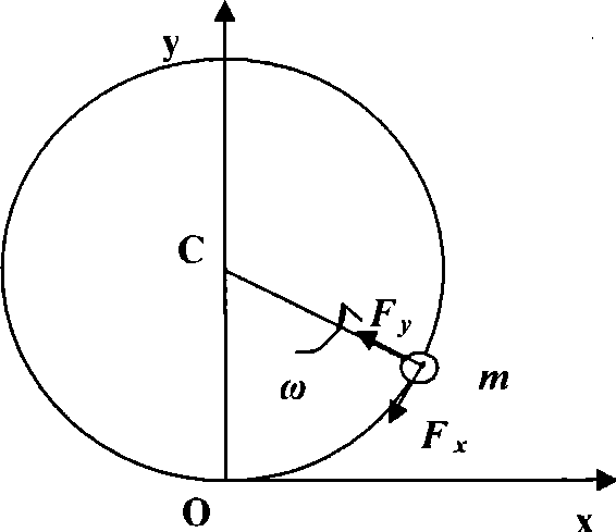
[0014] The present invention will be described in detail below in conjunction with the motion analysis of the vehicle during turning and braking.

[0015] Firstly, the vehicle is simplified as a mass point moving in a circle, the mass is m, such as figure 2 Shown. When the vehicle reaches O point, it is assumed that the vehicle is in a steady-state turning process, and the vehicle’s ground lateral force and centrifugal force are in balance. If the vehicle starts to brake at this time, the braking force F along the tangential direction is generated. x . At this time, on the one hand, the vehicle speed will continue to decrease, and on the other hand, due to the limitation of road conditions, the lateral force F y Decrease, which may cause the vehicle to lose lateral stability. In order to maintain the stability of the vehicle before and after braking in a curve, without steering intervention, you can control the braking force F x to fulfill. Within the ground adhesion limit, the c...


PUM


Abstract

The invention discloses a vehicle bend braking stability step control system which implements the step control on a total braking force Fx during the vehicle bend braking and the distribution of the total braking force on a front wheel and a back wheel by a braking force adjusting device according to different time points during the braking process of turning radius, vehicle speed and road attachment conditions during the vehicle bend braking. The upper limit of the total braking force Fx and the resultant force of a total lateral force Fy (equal to vehicle centrifugal force) form a vehicle limit adhesion force. The slip ratio of each wheel is controlled so as to maintain the total braking force Fx within the upper limit. Thus, the vehicle adhesion force is controlled within the limit adhesion force. When the vehicle speed during the braking process is lowered continuously, the centrifugal force is reduced continuously. The adjustment of the control system is not frequent according to a discipline that the upper limit of the total braking force of the vehicle changes with the braking time. The target slip ratio of the wheel at different time points is regulated according to time segments so as to ensure that the vehicle adhesion force during the braking process is within the limit adhesion force, so that the braking stability of the vehicle bend is guaranteed.

Description

technical field [0001] The invention relates to the braking stability control of the automobile curve, which realizes the braking stability control of the automobile curve through the step control of the braking force on each wheel at different time points in the braking process. Background technique [0002] The current automobile anti-lock braking system improves the braking stability of the vehicle by controlling the braking strength to prevent the wheels from locking, including the braking stability of the curve. The wheel load is reduced, which greatly reduces the anti-lock braking effect of the rear wheel, which often leads to the phenomenon of flicking when the vehicle brakes in a curve, which affects the braking stability of the vehicle. [0003] Based on the electronic braking force distribution system of the anti-lock braking system, the braking control algorithm has been improved in view of the above phenomenon, and the braking force of the front and rear axles ca...

Claims


Application Information

Patent Timeline
IPC IPC(8): B60T8/1755
Inventor 刘昭度王国业张彪李径亮叶阳付燕荣
Owner BEIJING INSTITUTE OF TECHNOLOGYGY
Why Eureka
Try Eureka