Field emission light source

A technology of field emission and light source, applied in the field of light source, can solve the problem of low luminous efficiency of field emission light source

Inactive Publication Date: 2009-03-11
TSINGHUA UNIV +1
View PDF0 Cites 18 Cited by
  • Summary
  • Abstract
  • Description
  • Claims
  • Application Information

AI Technical Summary

Problems solved by technology

In the planar light source, due to the shielding effect, there are few carbon nanotubes that can effectively emit electrons, so the luminous efficiency of the field emission light source of this design is not high

Method used


Image

  • Field emission light source
  • Field emission light source
  • Field emission light source

Examples


Embodiment Construction

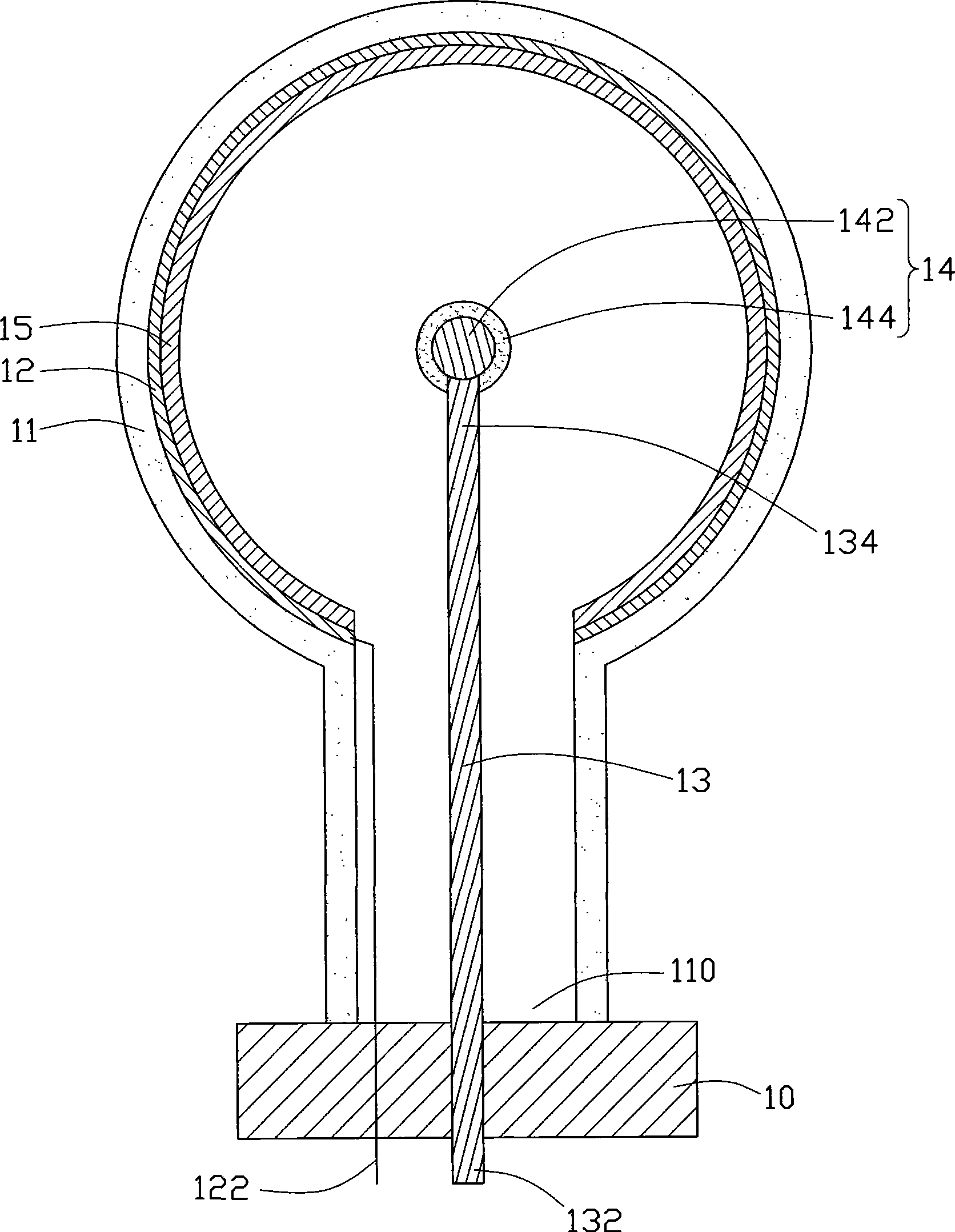
[0011] refer to figure 1 , The field emission light source 100 of the first embodiment of the technical solution includes a base 10 , a casing 11 , an anode 12 , a support 13 , and a cathode 14 .

[0012] The base 10 is made of insulating materials, such as glass, ceramics and the like. One end of the casing 11 has an opening 110 , and one end of the casing 11 having the opening 110 is installed on the base 10 so that the casing 11 and the base 10 jointly define a closed receiving space. The housing 11 can be made of transparent insulating material, such as glass or transparent ceramics. The casing 11 can be spherical, ellipsoidal or pear-shaped, and the casing 11 is pear-shaped in this embodiment.

[0013] The anode 12 is a layer of transparent conductive film such as indium tin oxide film or aluminum film. In this embodiment, the anode 12 is a transparent indium tin oxide film. The anode 12 is formed on the inner wall of the casing 11 . The wire 122 passes through the b...


PUM


Abstract

The invention relates to a field emission back light source which comprises a base, a supporting body, a shell, a cathode and an anode, wherein the shell is arranged on the base, and consequently, the shell and the base are designed into a containing space; the supporting body comprises a first end and a second end, the first end of the supporting body is connected with the base, the second end extends to the containing space from the first end, the cathode is connected to the second end, the anode is arranged on the inner wall of the shell, and fluorescent powder is arranged on the anode; the cathode comprises a basal body, the surface of the basal body is provided with a carbon nano tube, and the basal body is in a polyhedron shape, a spherical shape or an elliptical shape. In the field emission light source, the spherical cathode is adopted as an emission source, and a spherical surface light source which has high emission efficiency and stable emission is obtained.

Description

technical field [0001] The invention relates to a light source, in particular to a field emission light source. Background technique [0002] Field emission light source is a new type of light source. Its luminous principle is that under the action of an electric field, electron emitters such as metal tips and carbon nanotubes at low potentials emit electrons and bombard phosphors at high potentials to emit visible light. Please refer to " A Fully Sealed Luminescent Tube Based on Carbon Nanotube Field Emission", Mirko Croci, et al, Microelectronics Journal, vol. 35, p329-336 (2004). [0003] At present, research on the use of carbon nanotubes as a field emission light source is mainly concentrated in the field of planar light sources, which are mainly used in various backlight modules. In the planar light source, due to the shielding effect, there are few carbon nanotubes that can effectively emit electrons, so the luminous efficiency of the field emission light source of t...

Claims


Application Information

Patent Timeline
Patent Type & Authority Applications(China)
IPC IPC(8): H01J63/02H01J63/06
CPCH01J63/02H01J63/04
Inventor 付伟琦魏洋柳鹏刘亮范守善
Owner TSINGHUA UNIV
Why Eureka
Try Eureka