Laser welding method

A laser welding and laser beam technology, applied in laser welding equipment, welding equipment, household components, etc., can solve the problems of lack of flexibility, no laser welding application, etc., and achieve the effect of uniform measurement error, easy quality and high welding speed

Inactive Publication Date: 2009-03-11
CENCORP AUTOMATION OY
View PDF0 Cites 3 Cited by
  • Summary
  • Abstract
  • Description
  • Claims
  • Application Information

AI Technical Summary

Problems solved by technology

Therefore, there is no widespread application of laser welding in the industry
[0008] Furthermore, known non-laser welding methods have the disadvantage of lack of flexibility, for example, when changing the workpieces to be welded or their dimensions

Method used


Image

  • Laser welding method
  • Laser welding method

Examples


Embodiment Construction

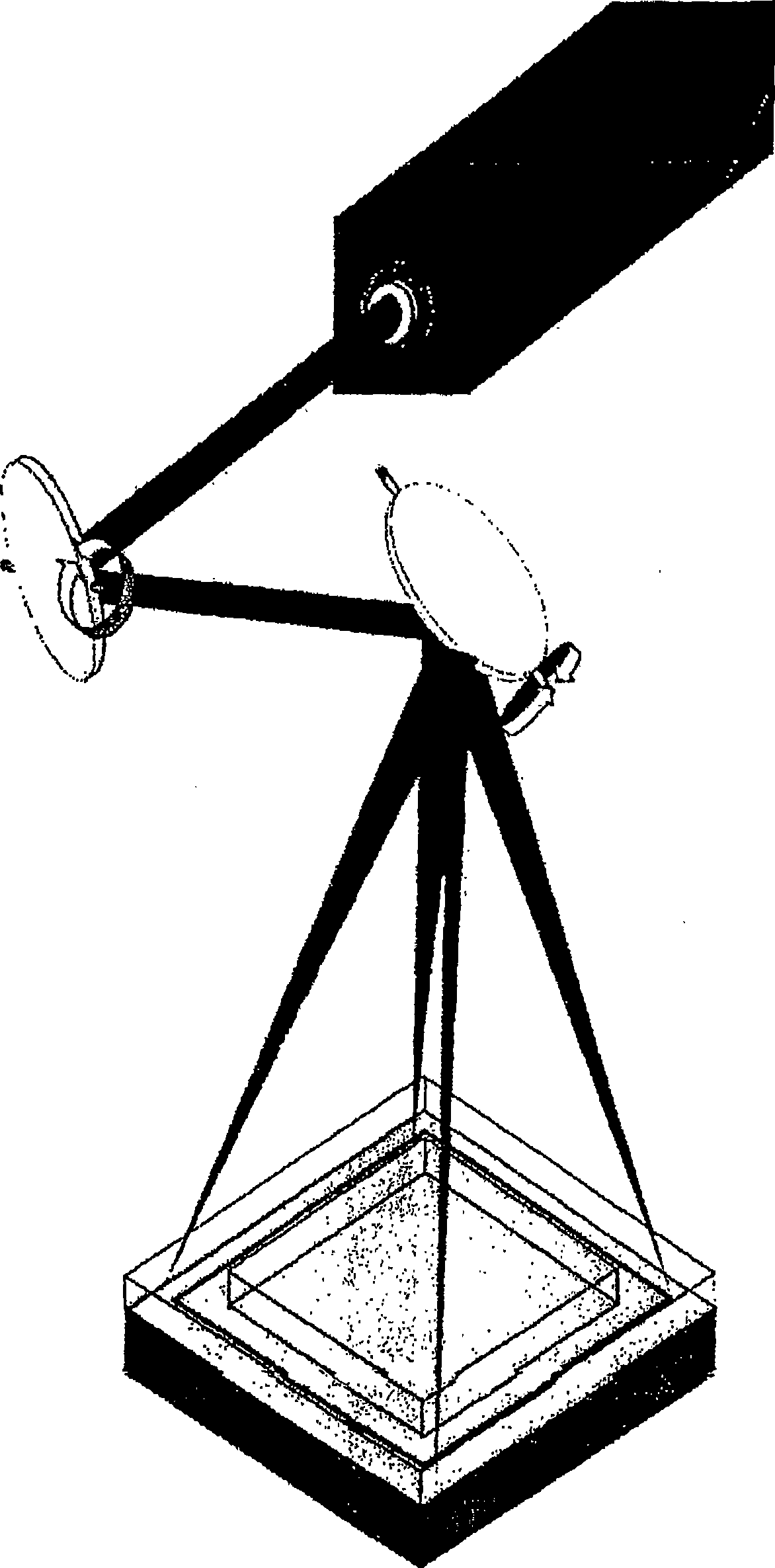
[0034] The method of the invention uses a scanner known from laser marking in plastic welding ( figure 1 )carry out testing. In this technique, a laser beam is scanned at high speed over the welding site by means of a metal fume thermal mirror. Due to the low thermal conductivity of plastics, the weld joint to be formed becomes progressively hotter and relatively uniform so that the entire weld joint melts almost simultaneously. In this method, the welding time is determined by the welding rate, ie the scan rate employed, the number of welding cycles employed and the size of the workpiece. The weld path forming the weld joint may be formed based on, for example, a CAD image.
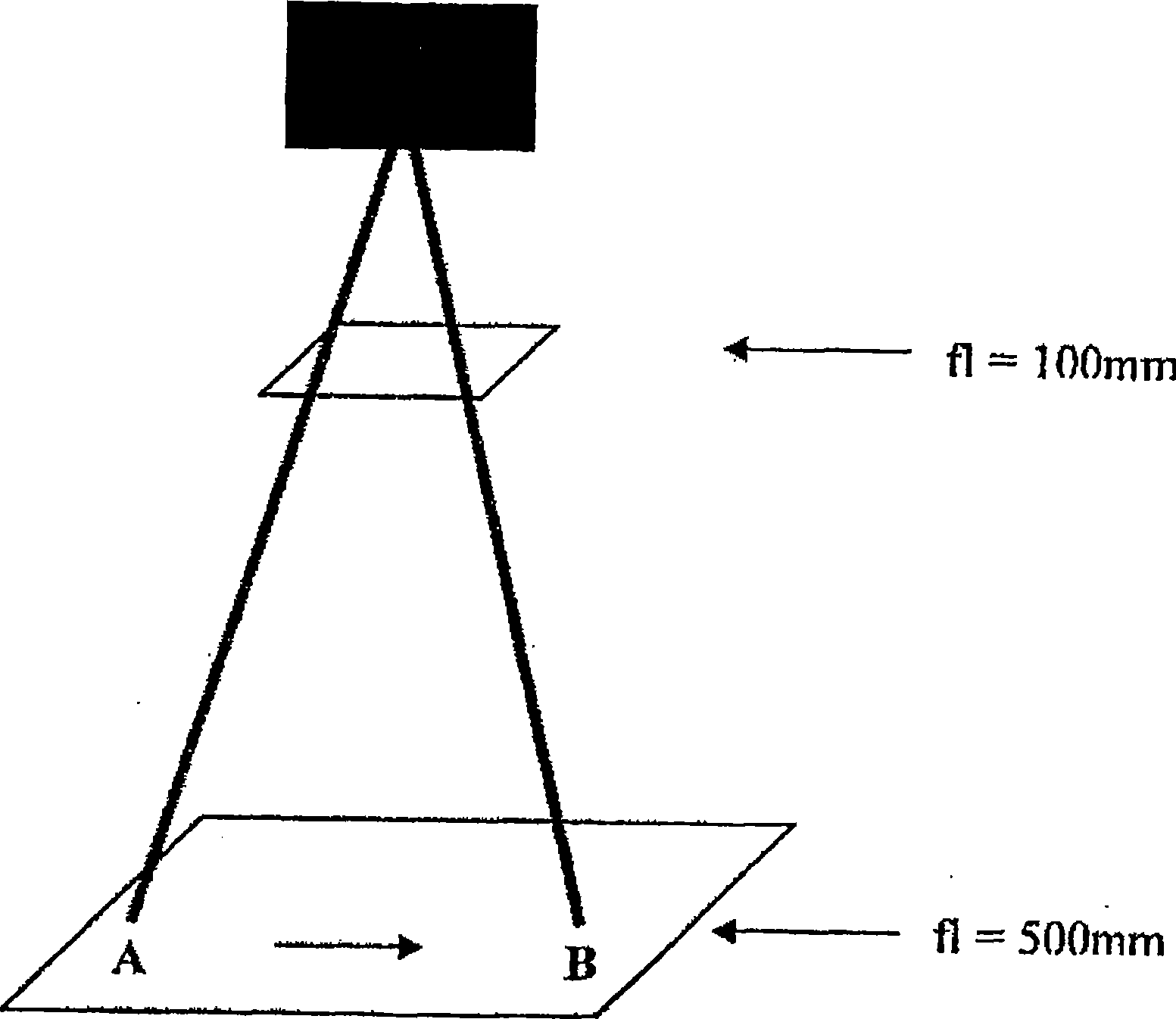
[0035] The speed and working area of ​​the scanner used in scanning welding are determined by the lens used. For example, in one test a known diode laser device used achieved a working area of ​​100 mm x 100 mm in which the size of the focus, ie the width of the weld, was 1.1 mm when a focal length of...


PUM


Abstract

The invention relates to a method for quick, flexible and quality laser welding of plastic articles. In the method, a laser beam is directed via scanner mirrors at an object being welded. According to the invention, in the method, the movement of the scanner mirrors is controlled and adjusted; and the moving speed of the laser beam is increased by increasing the focal distance to be more than 200mm; and the moving speed of the laser beam is arranged to be more than 10 m / s; and the laser beam is moved several times along a predetermined welding track.

Description

technical field [0001] The invention relates to a method as defined in the preamble of claim 1 for fast, flexible, high-quality laser welding of workpieces. Background technique [0002] There are various laser welding methods in the prior art. Furthermore, there are various laser welding applications for plastics in the prior art. A problem with known laser welding applications for plastics is that their introduction as industrial applications is limited by the hysteresis of these methods as well as the high price of laser equipment, eg in mass production applications. [0003] For example, the components of today's mobile phones are connected to each other mainly by means of ultrasonic welding. The method enables welding times of less than 0.5 seconds for various sized components of mobile phones. Current laser welding methods can only achieve the same welding rates when used on smaller components such as camera lenses. For example, when used in the display window of a...

Claims


Application Information

Patent Timeline
Patent Type & Authority Applications(China)
IPC IPC(8): B23K26/02B23K26/08B23K26/24B29C65/16
CPCB29C66/934B23K26/0876B29C65/16B29C66/93B29C65/1674B29C66/939B29C66/949B29L2031/3431B23K26/20B29C65/1661B29C65/08B29C66/91645B29C66/73921B23K26/24B29C66/41B29C65/1635B29C66/24245B29C66/1122B23K26/02B23K26/08B29C65/14
Inventor A·詹森
Owner CENCORP AUTOMATION OY
Why Eureka
Try Eureka