Oscillator device, optical deflecting device and image forming device

An oscillator and oscillation system technology, applied in the field of oscillator devices, to achieve the effects of precise control and slow power consumption

Inactive Publication Date: 2012-05-23
CANON KK
View PDF3 Cites 0 Cited by
  • Summary
  • Abstract
  • Description
  • Claims
  • Application Information

AI Technical Summary

Problems solved by technology

[0003] On the other hand, in the resonance type optical deflection device, since the deflection angle (displacement angle) of the mirror changes sinusoidally in principle, the angular velocity is not constant

Method used


Image

  • Oscillator device, optical deflecting device and image forming device
  • Oscillator device, optical deflecting device and image forming device
  • Oscillator device, optical deflecting device and image forming device

Examples


no. 1 example

[0050] An oscillator device according to a first embodiment of the present invention will now be described.

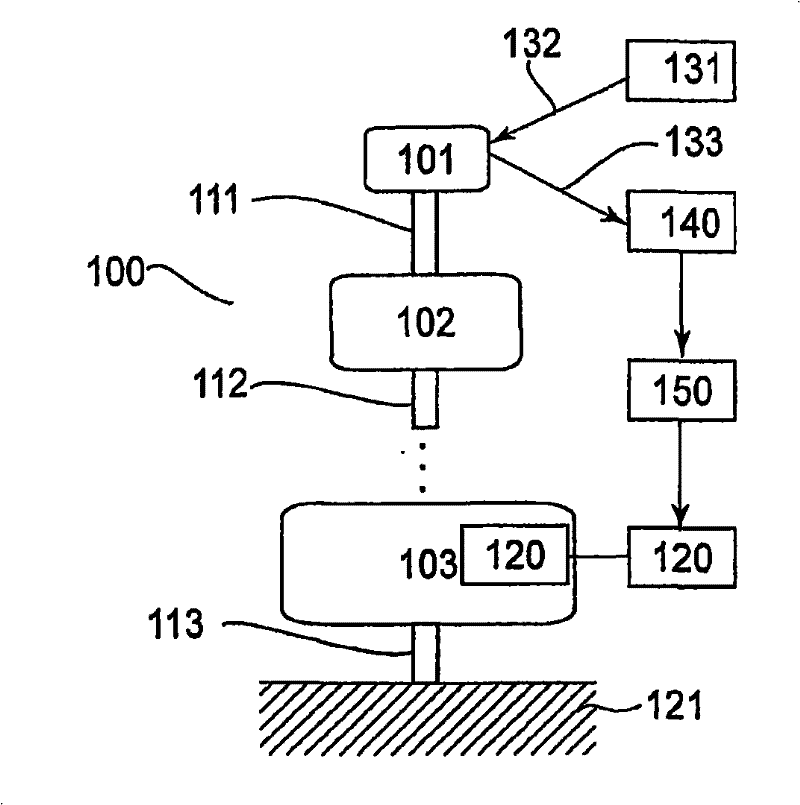
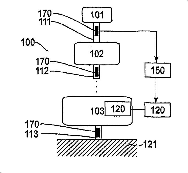
[0051] like Figure 1A and 1B As shown in , the oscillator device of this embodiment may include: an oscillating system including at least a first oscillator 101, a second oscillator 102, a first torsion spring 111 and a second torsion spring 112; and a support system 121, used to support the oscillation system. The first torsion spring may connect the first oscillator and the second oscillator to each other. The second torsion spring may be connected to the second oscillator so that it has a common torsion axis with respect to the first torsion spring. The oscillation system of this embodiment may have at least two oscillators and at least two torsion springs. Therefore, if Figure 1A and 1B As shown in , it can include three or more oscillators and three or more torsion springs.

[0052] The oscillator device may further comprise a drive system 120 for applyin...

no. 2 example

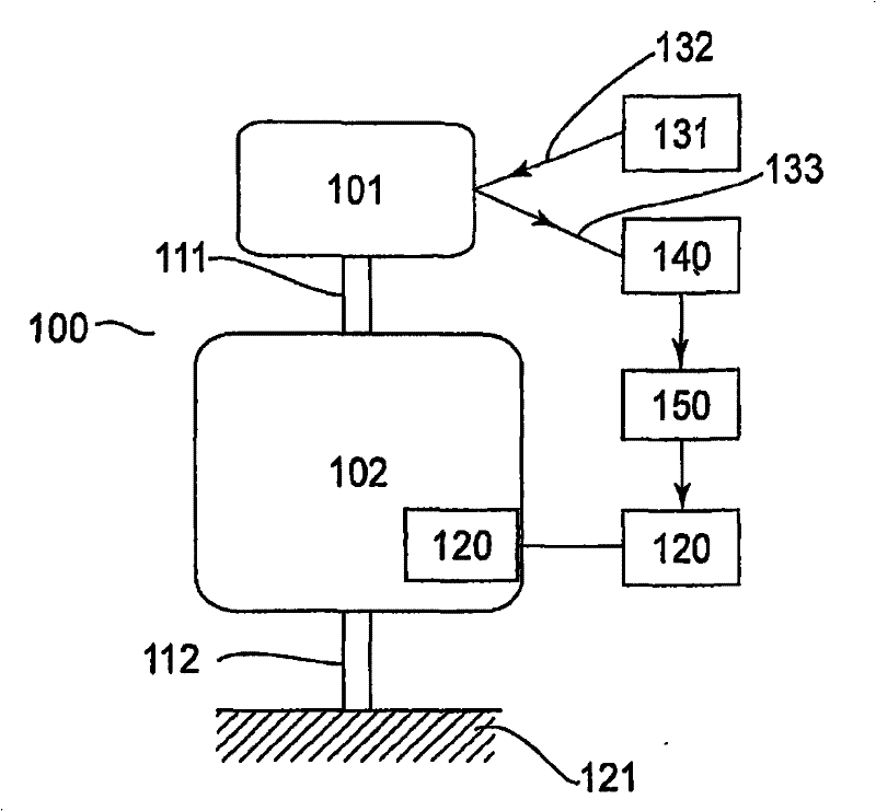
[0086] An oscillator device according to a second embodiment of the present invention will now be described. like Figure 2A and 2B As shown in , the oscillator device of this embodiment may include: an oscillating system including a first oscillator 101, a second oscillator 102, a first torsion spring 111 and a second torsion spring 112; The support system 121 of the oscillation system. The first torsion spring may connect the first oscillator and the second oscillator to each other. The second torsion spring can connect the support system and the second oscillator 102 so that it has a common torsion axis with respect to the first torsion spring.

[0087] The oscillator device may further include: a drive system 120 for applying a drive force to the oscillation system; a drive control system 150 for adjusting the drive system; A signal generating device that generates time information related to time when the displacement angle is shifted. This signal generating device c...

no. 3 example

[0107] An oscillator device according to a third embodiment of the present invention will be described. Figure 2A is a block diagram of an optical deflection device having an oscillator device according to this embodiment. The basic structure is the same as the oscillator device according to the aforementioned first or second embodiment. In this example, as Figure 3A As shown in , in order to detect the scanning light 133, first and second light receiving elements are provided at positions of first and second displacement angles.

[0108] In this example, too, if A 1 , ω 1 and Indicate the amplitude, angular frequency and phase of the first oscillatory action, with A 2 , ω 2 and Denote the amplitude, angular frequency and phase of the second oscillating action, and use t to denote the time, then the deflection angle θ of the optical deflecting device can be expressed by the aforementioned formula (3-1).

[0109] Furthermore, if using A 1 and ω 1 Indicates the a...


PUM


Abstract

Disclosed is an oscillator device that includes an oscillating system having a first oscillator, a second oscillator, a first torsion spring for connecting the first and second oscillators each other, and a second torsion spring being connected to the second oscillator and having a common torsional axis with the first torsion spring; a supporting system for supporting the oscillating system; a ' driving system for driving the oscillating system so that at least one of the first and second oscillators produces oscillation as can be expressed by an equation that contains a sum of a plurality oftime functions; a signal producing system for producing an output signal corresponding to displacement of at least one of the first and second oscillators; and a drive control system for controlling the driving system on the basis of the output signal of the signal producing system so that at least one of amplitude and phase of the time function takes a predetermined value.

Description

technical field [0001] The present invention relates to an oscillator device having a plurality of oscillators, and more particularly to an oscillator device applicable in an optical deflection device. In another aspect, the present invention relates to a scanning type display such as a laser beam printer or a digital copying machine or an image forming apparatus having such an optical deflecting device. Background technique [0002] Compared with conventional scanning optical systems with rotating polygonal mirrors (polygon mirrors), the recently proposed resonant optical deflection device has the following advantageous features: the optical deflection device can be made considerably smaller in size, power consumption is slow, and theoretically there are no mirrors. The surface of the surface is sloped. [0003] On the other hand, in the resonance type optical deflection device, since the deflection angle (displacement angle) of the mirror changes sinusoidally in principl...

Claims


Application Information

Patent Timeline
Patent Type & Authority Patents(China)
IPC IPC(8): G02B26/08
CPCG02B26/0833B81B2201/042G02B26/085G02B26/105
Inventor 藤井一成古川幸生秋山贵弘庄司龙平铃木总一郎松尾信平補伽达也饭村绅一郎
Owner CANON KK
Why Eureka
Try Eureka