Numerical control polishing machine for optical elements

A technology of optical components and machine tools, which is applied in the field of improvement of optical component manufacturing equipment, can solve the problems of difficult control of precision and low efficiency, and achieve the effects of ensuring high certainty, ensuring operation stability, and saving man-hours

Active Publication Date: 2010-08-11
常州皓研智能科技有限公司
View PDF0 Cites 0 Cited by
  • Summary
  • Abstract
  • Description
  • Claims
  • Application Information

AI Technical Summary

Problems solved by technology

[0010] Provides a CNC polishing machine tool for medium and large diameter aspheric optical elements, which can solve the problems of difficult control of precision and low efficiency in traditional polishing methods for optical elements

Method used


Image

  • Numerical control polishing machine for optical elements
  • Numerical control polishing machine for optical elements
  • Numerical control polishing machine for optical elements

Examples


Embodiment 1

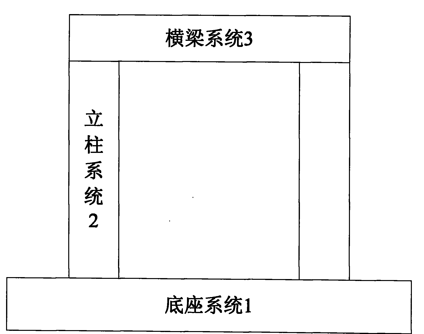
[0031] As shown in Figure 1, 1 is the base system, 2 is the column system, and 3 is the beam system;

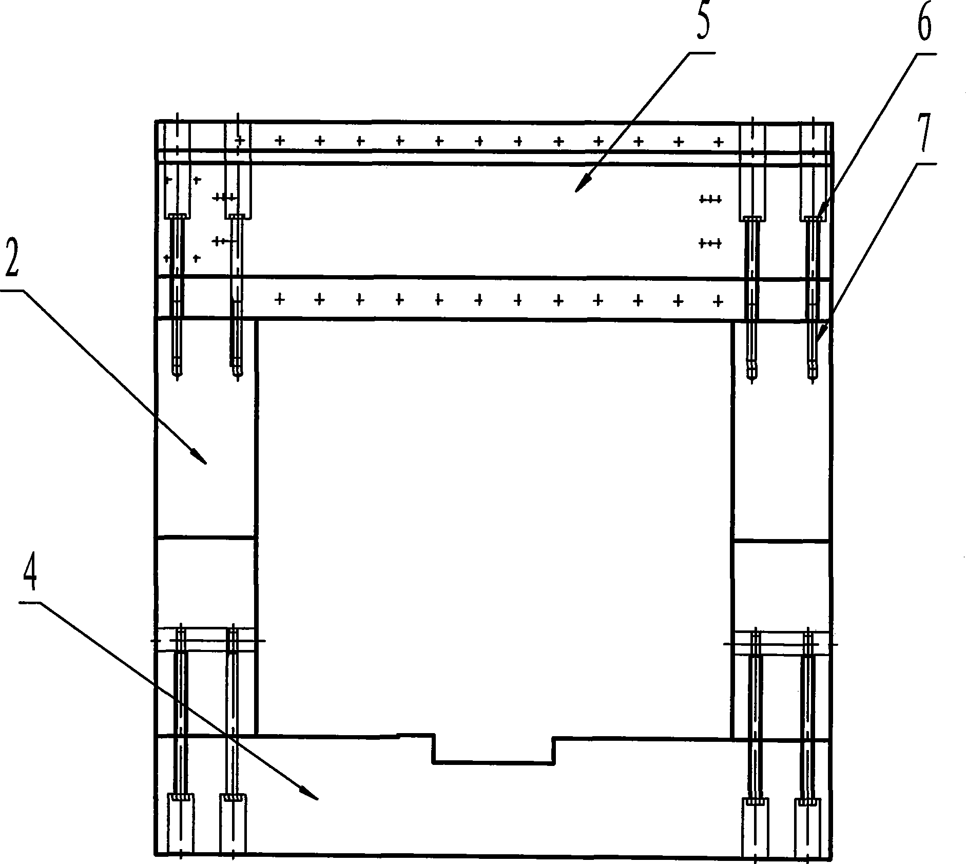
[0032] As shown in Figure 2, 4 is the base of the bed, 5 is the beam, 6 is the screw, and 7 is the embedded nut;

[0033] As shown in Figure 3, 8 is the connecting nut between the column and the bed base, and 9 is the connecting bolt between the column and the bed base;

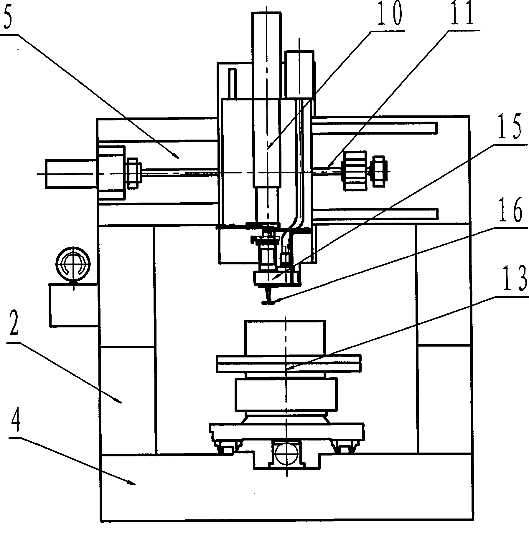
[0034] As shown in Figure 4, 10 is the Z axis of the numerical control axis, 11 is the Y axis of the numerical control axis, 13 is the A axis of the numerical control axis, 15 is the power planetary polishing head, and 16 is the polishing mold;

[0035] As shown in Figure 5, 12 is the X axis of the numerical control axis, and 14 is the rotary feed system of the C axis;

[0036] As shown in Figure 6, 17 is the X-axis double nut pre-tightening structure, 18 is the A-axis worm gear pair, 19 is the A-axis gear pair, 20 is the A-axis servo motor, 21 is the Y-axis servo motor, and 22 is the Y-axis precision Ball...


PUM


Abstract

The invention relates to a digital control polishing machine tool of a non-spherical optical element with large caliber, which pertains to the technical filed of optical machine building and is characterized in that: the machine tool essentially consists of a base system, an upright column system and a crossbeam system; the base system comprises a base, an X-axis feeding system, an A-axis overturning feeding system and a C-axis revolved feeding system; the crossbeam system comprises a crossbeam, a Y-axis feeding system, a Z-axis feeding system, a power planetary polishing head and a polishingdie. A four link rod locating mechanism is adopted to realize 16 translation of the polishing die; the machine tool has the advantages that: five-axis digital control and the manner of four-axis linking motion are adopted in the digital control polishing machine tool of the optical element; the overturning and rotating structure of a work piece is utilized, thus causing the polishing position to keep horizontal and ensuring the high determinacy of a removal function; the machine tool is controlled by adopting non-clearance transmission and a high-precision pneumatic system, thereby ensuring the operating stability of a polishing process and realizing the digital control processing of the optical element.

Description

technical field [0001] The invention belongs to the technical field of optical machinery manufacturing and relates to an improvement of optical element manufacturing equipment. Background technique [0002] The application of optical components in optoelectronic systems is becoming more and more extensive, and the processing technology of optical components seriously affects the application of optical components. At present, the processing of optical components in China is mainly based on the traditional manual processing method, which has low efficiency and difficult control of processing accuracy, which cannot meet the requirements of modern optical system applications. As the infrastructure for the development of modern optical component manufacturing technology, CNC machine tools are the key to the effective removal of optical components. [0003] Foreign optical component polishing technology: [0004] Developed countries took the lead in proposing the technical idea ...

Claims


Application Information

Patent Timeline
Patent Type & Authority Patents(China)
IPC IPC(8): B24B29/02B24B47/20
Inventor 王春阳聂凤明吴庆堂刘劲松王大森
Owner 常州皓研智能科技有限公司
Why Eureka
Try Eureka