Sheet adsorption device, transport device, and image forming apparatus

A technology of adsorption device and image, applied in printing device, transportation and packaging, printing and other directions, can solve the problems of increasing noise, not getting adsorption effect, generating air flow, etc.

Active Publication Date: 2009-03-18
SEIKO EPSON CORP
View PDF1 Cites 23 Cited by
  • Summary
  • Abstract
  • Description
  • Claims
  • Application Information

AI Technical Summary

Problems solved by technology

[0007] In the case that the size of the recording medium does not correspond to the pre-arranged porous adsorption surface, or the recording medium is inclined and deviates from the porous adsorption su

Method used


Image

  • Sheet adsorption device, transport device, and image forming apparatus
  • Sheet adsorption device, transport device, and image forming apparatus
  • Sheet adsorption device, transport device, and image forming apparatus

Examples


no. 1 approach

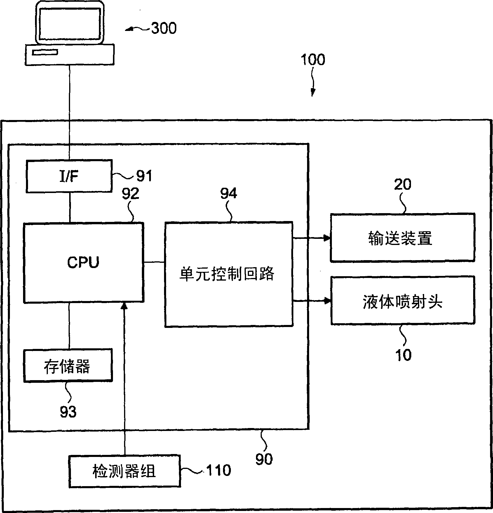
[0064] figure 1 A block diagram showing the overall configuration of the image forming apparatus 100 of this embodiment.

[0065] The image forming apparatus 100 that receives print data from a computer 300 as an external device controls the conveyance device 20 and the liquid jet head 10 through the controller 90 to form an image on the recording medium S that is a sheet. In addition, the condition in the image forming apparatus 100 is monitored by the detector group 110 , and the controller 90 controls the transport device 20 and the liquid jet head 10 based on the detection result.

[0066] The controller 90 is a control unit for controlling the image forming apparatus 100 . Interface unit (I / F) 91 is used to transmit and receive data between computer 300 and image forming apparatus 100 . CPU 92 is an arithmetic processing unit for controlling the overall image forming apparatus 100 . The memory 93 secures an area for storing programs of the CPU 92 , a work area, and th...

no. 2 approach

[0142] Figure 9 A schematic cross-sectional view of the image forming apparatus 200 of this embodiment is shown in . The image forming apparatus 200 of the present embodiment prints continuously on the recording medium S that is roll paper. The point different from the first embodiment is that the belt 40 is not included in the conveying device 85 .

[0143] exist Figure 9 Among them, the transport device 85 includes a paper feed roller 71 , a paper take-up roller 72 , and a sheet suction device 80 .

[0144] The recording medium S is conveyed from the paper feed roller 71 to the paper take-up roller 72 while being attracted to the sheet suction surface 612 . The sheet suction device 80 includes a fan 50 as a suction mechanism, and a static pressure control unit 60 .

[0145] In the sheet suction device 80 of the present embodiment, the sheet suction surface 612 is the same as that of the first embodiment. Figure 5 , Figure 7 and Figure 8 The side of the belt suppo...

no. 3 approach

[0152] Figure 10 A schematic cross-sectional view of the sheet suction device 66 included in the image forming apparatus of this embodiment is shown in . In the figure, arrows indicate the flow path of the gas in the case of suction by the fan 50 . In addition, a white arrow indicates the direction in which the recording medium S is transported. In addition, in this embodiment, the structure other than the sheet|seat adsorption|suction device 66 is the same as that of 1st Embodiment. Specifically, the static pressure controller 67 disposed between the belt 40 and the fan 50 in the sheet suction device 66 controls the suction state of each suction hole 42 , thereby switching the first state and the second state of the communication channel 600 .

[0153] Such as Figure 10 As shown, the sheet suction device 66 includes: a belt support plate 68 as a first plate-shaped member capable of supporting the recording medium S placed on the belt 40 via the belt 40; a main body 69 as...


PUM


Abstract

The invention provides a sheet adsorption device, a transport device and an image forming apparatus, for obtaining stable adsorbability, and little noises caused by air flowing and alternation of the load of a negative pressure generating mechanism and reduced power consumption, independent of the size and gradient of the adsorbent sheet. A flow path shifting unit (70) selects the section of the flow path according to the presence of recording media for covering a suction hole (42). Accordingly, air flow at the suction hole (42) not covered by the recording media is relatively reduced, therefore, no matter of the size and the gradient of the adsorbent sheet, stable adsorbability is obtained, the sheet adsorption device (30) is obtained, wherein the noises and alternation of the adsorbent load caused by air flow are reduced.

Description

technical field [0001] The present invention relates to a sheet suction device, a transport device using the same, and an image forming device using the same. Background technique [0002] As a device for sucking a sheet such as a recording medium, a device that sucks one side of the sheet by a negative pressure generating mechanism is known. In addition, devices using electrostatic force and devices using a method of pressing a sheet with a magnet or the like are known. [0003] The device that attracts the sheet by the negative pressure generating mechanism has little influence on electrical components due to static electricity, and since there is no magnet, etc. on one side of the sheet, almost the entire area of ​​one side of the sheet can be used for printing, etc. And so superior. [0004] It is known that on a support plate formed with a plurality of air holes, a porous belt having a porous adsorption surface formed with a plurality of air holes is moved, and suctio...

Claims


Application Information

Patent Timeline
IPC IPC(8): B41J13/00B65H5/22
Inventor 依田兼雄林贵人矢岛康司盐原悟金田聪
Owner SEIKO EPSON CORP
Why Eureka
Try Eureka