
Monitoring system of reconfigurable static reactive compensation/DC deicing composite apparatus

A technology of static reactive power compensation and monitoring system, applied in the direction of comprehensive factory control, comprehensive factory control, electrical program control, etc., can solve the problem of no such device application, and achieve the effect of ensuring consistency and avoiding misoperation

Inactive Publication Date: 2011-03-23
STATE GRID CORP OF CHINA +2
View PDF0 Cites 0 Cited by
  • Summary
  • Abstract
  • Description
  • Claims
  • Application Information

AI Technical Summary

Problems solved by technology

[0003] At present, there is no application of such devices in China

Method used


Image

  • Monitoring system of reconfigurable static reactive compensation/DC deicing composite apparatus
  • Monitoring system of reconfigurable static reactive compensation/DC deicing composite apparatus
  • Monitoring system of reconfigurable static reactive compensation/DC deicing composite apparatus

Examples


Embodiment 1

[0022] Example 1: The working mode of the composite device is restructured into the mode of the static var compensation device

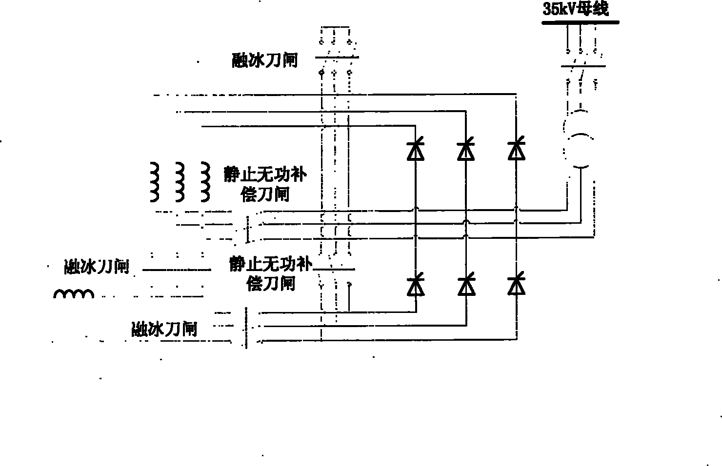
[0023] as attached Figure 4 As shown, the specific realization method of reconfiguring the working mode of the compound device into a static var compensation device is given. The monitoring system closes the static var compensation knife switch and opens the ice-melting knife switch after receiving the static var compensation working mode switching command and the knife switch automatic operation command from the operating personnel on duty. After the knife gate operation is completed, the primary equipment connection method is as follows: the wiring of the thyristor valve group forms an anti-parallel connection, three phase-controlled reactors are respectively connected in series behind each phase of the thyristor valve group, and the three-phase thyristor valve group is connected in a delta connection form. The low voltage side of the rectifier t...

Embodiment 2

[0024] Example 2: The working mode of the compound device is reconfigured to the mode of the DC ice-melting device

[0025] as attached Figure 5 As shown, the specific implementation method of reconfiguring the working mode of the compound device into a DC ice melting device is given. The monitoring system will open the static var compensation knife switch and close the ice melting knife switch after receiving the ice melting working mode switching command and the knife switch automatic operation command from the operator on duty. After the knife switch operation is completed, the primary equipment connection method is: the positive and negative poles of two sets of thyristor valve groups are connected end-to-end to form a series connection form, and three phase-controlled reactors are connected in parallel as smoothing reactors to the output side of the DC bus. The thyristor valve group has a large margin in the first design, and the reconfiguration method does not need to ...


PUM


Abstract

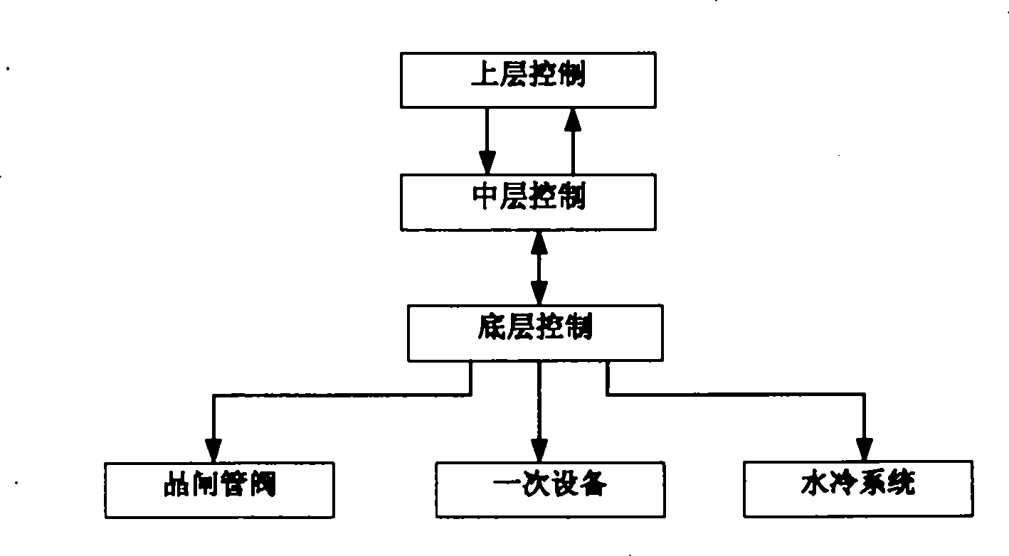
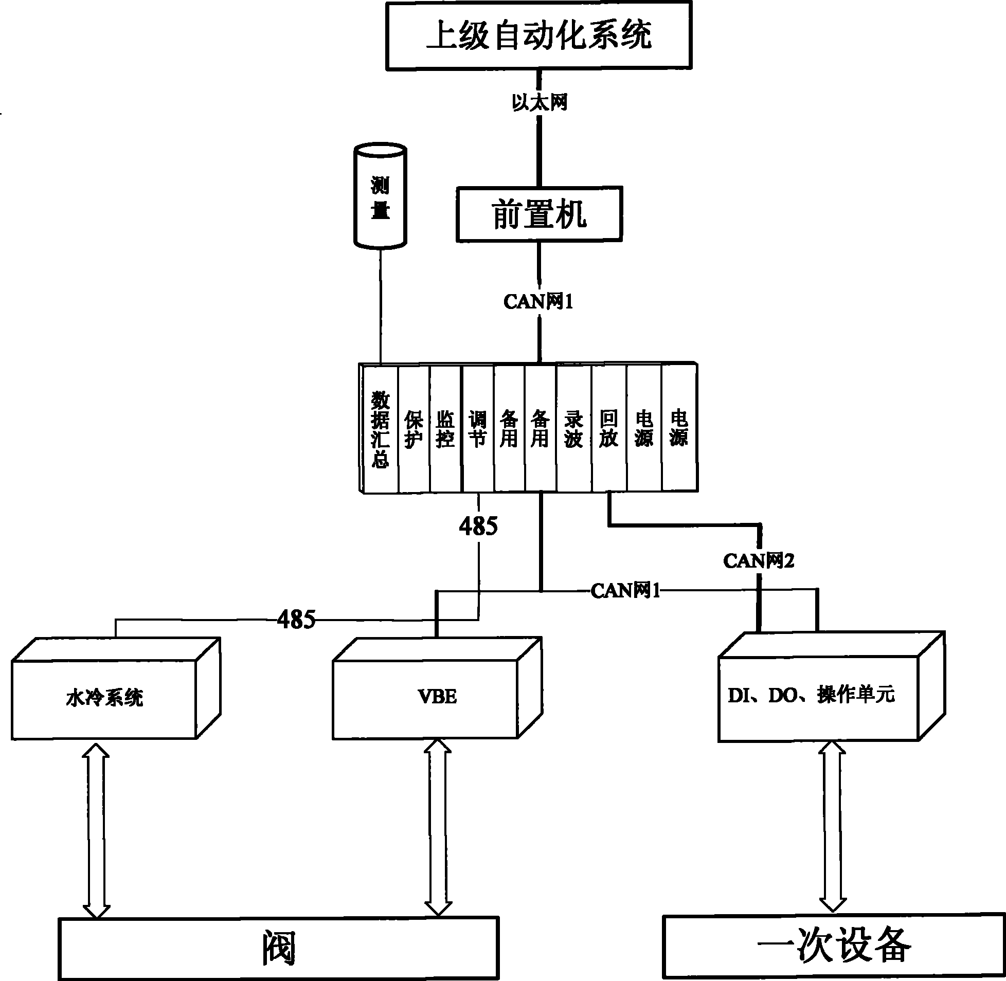
The invention provides a monitoring system of a reconfigurable type SVC / DC-based deicing composite device. The system utilizes a layered distributed structure including a bottom layer, a middle layer and an upper layer, which comprises a superior automation system, a communication supervisor, a primary equipment microcomputer protection unit, a front end computer, a data collecting unit, a protecting logic unit, a monitor unit, an adjusting unit, an input and output unit, an operating executing unit, and water cooling system monitoring and valve base electronics. By communicating with the superior automation system to automatically perform switching operation of relative switches connected with the primary equipment, the monitor can realize reconfiguration of two operating modes including the SVC and the deicing, and exchanges information with a transformer substation integral automation system, thereby guaranteeing consistency of the operating mode and the working status of the primary equipment, meeting system requirements upon both normal condition and ice coating conditions in winter.

Description

technical field [0001] The invention belongs to the technical field of power electronics application, and mainly relates to a monitoring system of a composite device of a reconfigurable static var compensator and a DC ice melting device. Background technique [0002] At the beginning of 2008, severe rain, snow and freezing disasters occurred in Central China, Southwest my country, and East China. The power grid facilities were seriously covered with ice and snow, and frequent tripping of disconnected and towered lines caused huge losses to the power grid. In some areas, the power grid was even destroyed. hit. Due to the small time and frequency of ice disasters, if the DC ice melting equipment can only be used as an ice melting device, its economic efficiency is poor. The monitoring system of the composite device of the reconfigurable static var compensation device and the DC deicing device, in addition to meeting the needs of 220kV and above voltage level transmission lines...

Claims


Application Information

Patent Timeline
Patent Type & Authority Patents(China)
IPC IPC(8): G05B19/418
CPCY02P90/02
Inventor 徐丽娟徐桂芝柴斌张皎荆平张帆
Owner STATE GRID CORP OF CHINA
Learn More