
Both feet humanoid robot based on passive movement mode

A passive motion and robotic technology, applied in the field of robotics, can solve the problems of large motor output torque, high motor cost, and motor wear, and achieve reasonable motion and good compression resistance

Inactive Publication Date: 2009-03-25
PEKING UNIV
View PDF0 Cites 19 Cited by
  • Summary
  • Abstract
  • Description
  • Claims
  • Application Information

AI Technical Summary

Problems solved by technology

However, this method has many disadvantages: 1. If each joint needs to be driven by a motor, the output torque of the motor will be relatively large at certain motion moments, which will not only cause severe wear and tear on the motor itself, but also to achieve this. Torque requirements, the cost of the motor that needs to be matched is also relatively high
2. If the motors are used to drive the joints, since not all the motor energy does effective work, the energy usage efficiency is extremely low
Therefore, in an offline environment, when the stored energy is limited, the continuous working time of the mechanical legs driven by motors is relatively low, which is very unsuitable for long-term field work.
3. When the traditional mechanical legs rub and collide with the ground during movement, the impact resistance requirements of the entire body are relatively high, but most motors have low impact resistance, which makes the existing mechanical legs relatively low in motion ability and far away. Failure to meet people's expectations and actual needs
However, due to the main open-loop control, the ability to interact with the environment is not strong, and it is not suitable for field operations or medical applications.

Method used


Image

  • Both feet humanoid robot based on passive movement mode
  • Both feet humanoid robot based on passive movement mode
  • Both feet humanoid robot based on passive movement mode

Examples


Embodiment Construction

[0016] The structure of the present invention will be described in detail below through embodiments and in conjunction with the accompanying drawings.

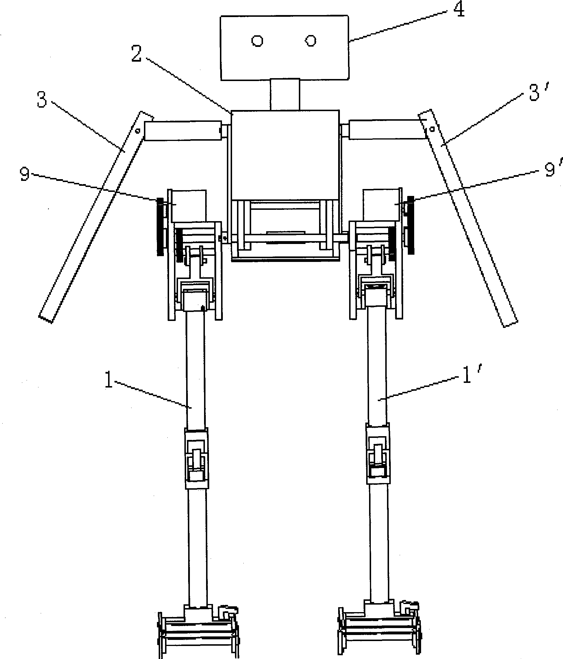
[0017] like figure 1 As shown, the present invention includes left and right bionic elastic mechanical legs 1, 1' (patent applied for separately, application number: 2007101201578), transmission trunk 2, left and right mechanical arms 3, 3' and mechanical head 4.

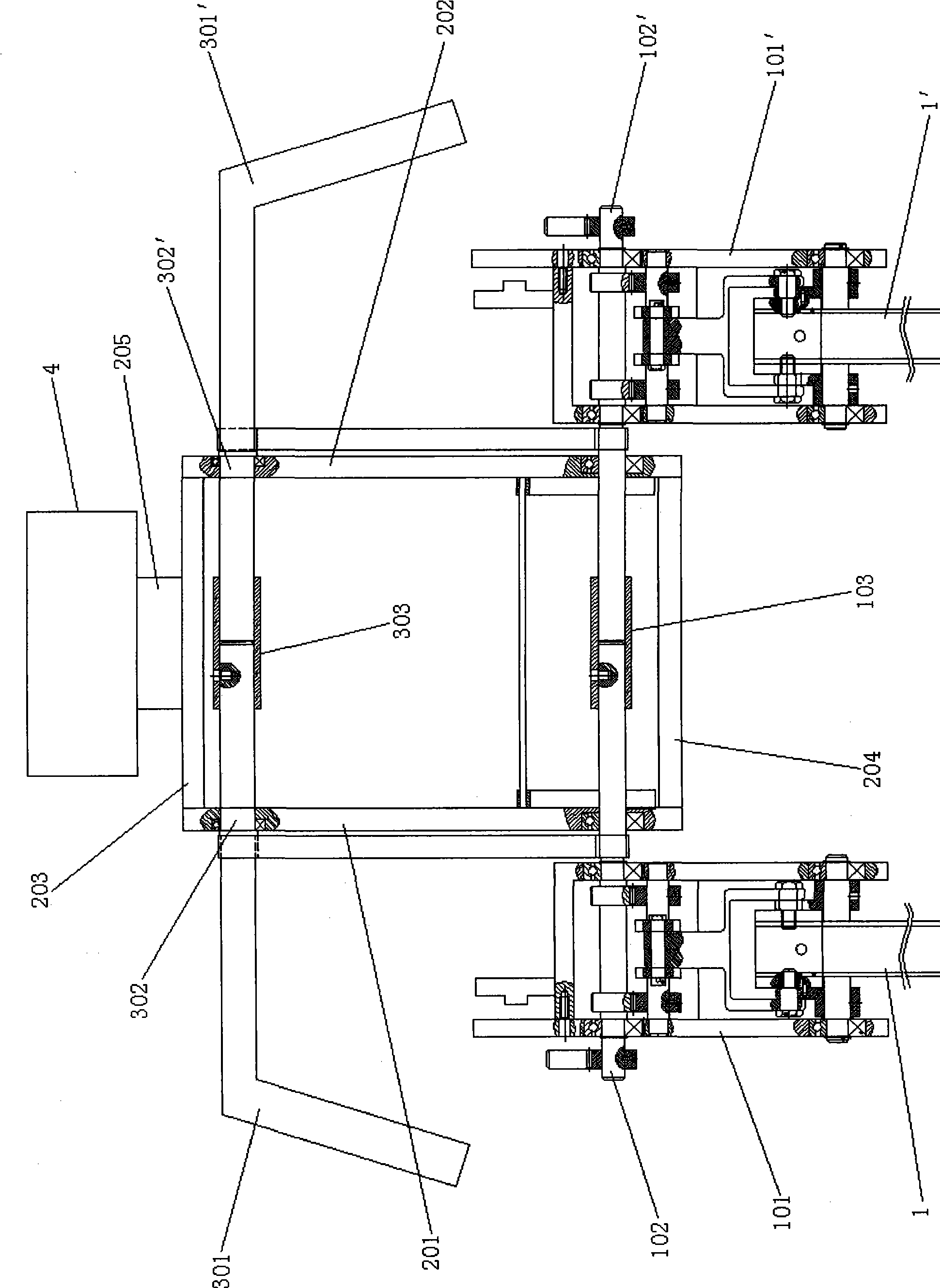
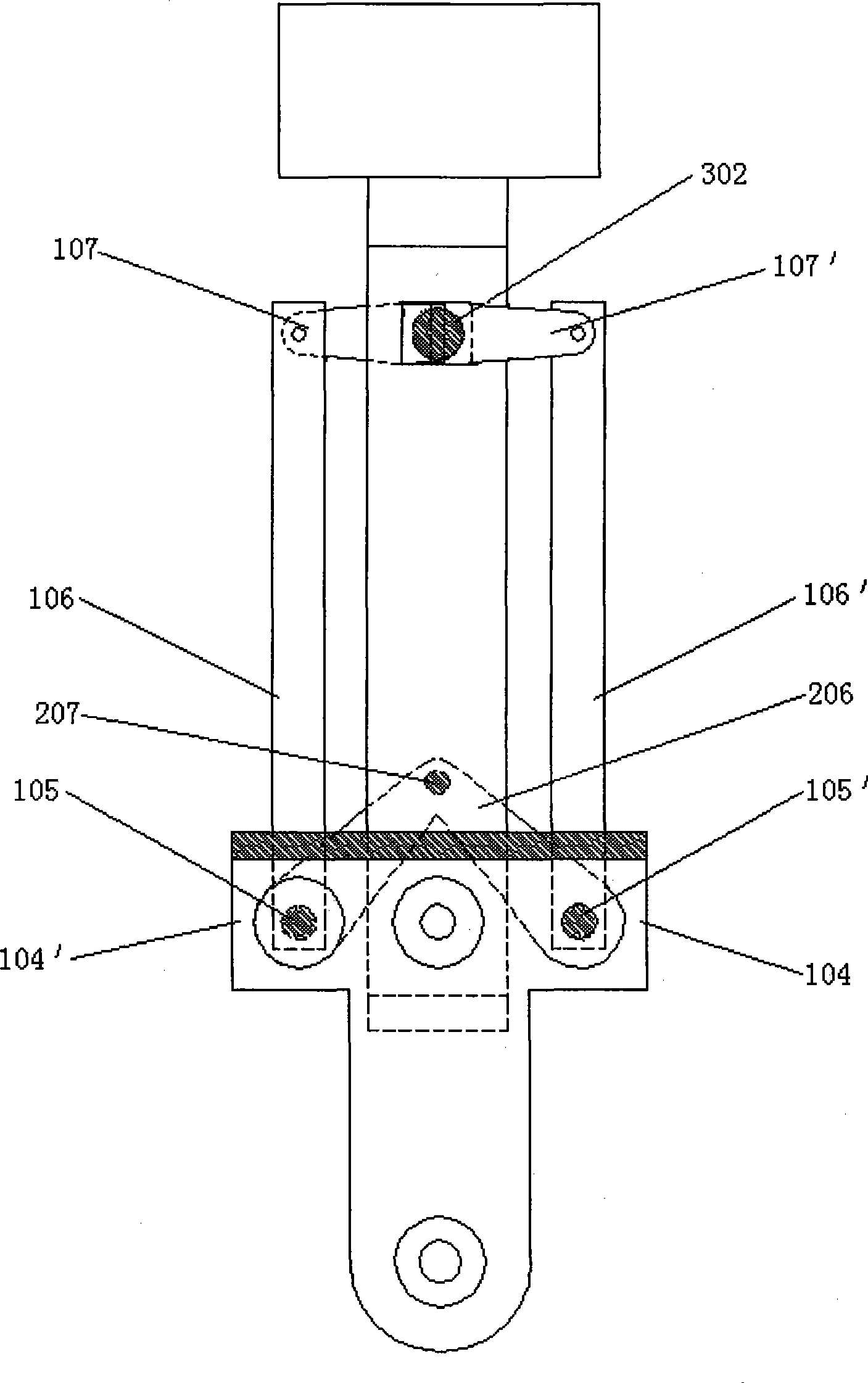
[0018] like figure 2 As shown, the transmission trunk 2 is surrounded by left and right trunk fixing frames 201, 202 and upper and lower trunk connecting frames 203, 204 fixedly connected. Mechanical head 4 is fixedly connected with upper trunk connecting frame 203 by neck 205, and mechanical head 4 can not rotate, and only plays a decorative role at present. The left and right hip shells 101, 101' of the left and right bionic elastic mechanical legs 1, 1' are respectively connected to one end of the left and right hip half shafts 102, 102', and the left and righ...


PUM


Abstract

The invention relates to a double-foot human-like robot based on a passive movement style, which is characterized in that: the robot includes a bionic elastic mechanical legs, a transmission trunk, mechanical drive arms; two convex arms are arranged respectively at the front and the back of the hip shell of the two mechanical legs, two extending sections of the convex arms are respectively and fixedly connected with one end of a driving shaft of the upper limb. The other end of driving shaft of the upper limb is connected with one end of a connecting rod, one end of which is fixedly connected with one end of a rocker. And the other end of rocker is fixedly connected with a limb half shaft arranged on the transmission trunk lateral side. The mechanical arm includes an upper limb; one end of the upper limb half shaft is connected with the upper limb with the other end respectively threaded through the upper part of the transmission trunk and is in butt joint. The butt joint position of the upper limb half shaft is provided with a connecting tube, wherein, the upper limb half shaft is fixed with the connecting tube through a screw with the other upper limb half shat loosely matched with the connecting tube. The invention adopts an active and passive combination movement style and realizes an energy optimization of the double-foot movement through a passive mechanical structural linkage limb, is wildly applicable to the research of footed robots and the development of service robots and the medical and health fields.

Description

technical field [0001] The invention relates to a robot, in particular to a biped humanoid robot based on passive motion. Background technique [0002] With the development of robot technology, the use of robots has become more and more extensive, and it has begun to transform from mechanical to intelligent and special types, from traditional industrial fields to education, military, security, space, underwater, medical and life services, etc. domain penetration. [0003] Traditional biped humanoid robots use motors as motion drives, and all joints are driven by motors and controlled by computers. When moving, the computer sends instructions to each joint, controlling the angle of each moment they stride. Although this method can precisely control the motion of the humanoid robot, it requires a complex, fast and precise control mechanism. Studies have shown that pure motor drive not only has low energy utilization rate, but also cannot realize complex movements with large...

Claims


Application Information

Patent Timeline
IPC IPC(8): B25J3/04B25J9/08B62D57/028
Inventor 王启宁朱金营麦金耿王龙
Owner PEKING UNIV
Learn More