Forming method for stereoscopic pattern of plastic rubber member

A technology of three-dimensional pattern and forming method, which is applied in the direction of coating, etc., and can solve the problem of not being able to print three-dimensional patterns

Inactive Publication Date: 2009-03-25
KANGZHUN ELECTRONICS TECH KUNSHAN +1
View PDF0 Cites 6 Cited by
  • Summary
  • Abstract
  • Description
  • Claims
  • Application Information

AI Technical Summary

Problems solved by technology

[0003] However, the use of in-mold transfer printing technology can only form flat patterns on plastic parts, but cannot print three-dimensional patterns

Method used


Image

  • Forming method for stereoscopic pattern of plastic rubber member
  • Forming method for stereoscopic pattern of plastic rubber member
  • Forming method for stereoscopic pattern of plastic rubber member

Examples


Embodiment Construction

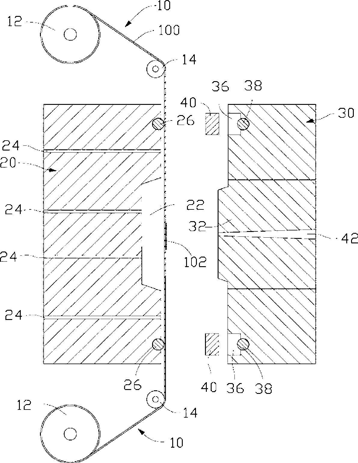
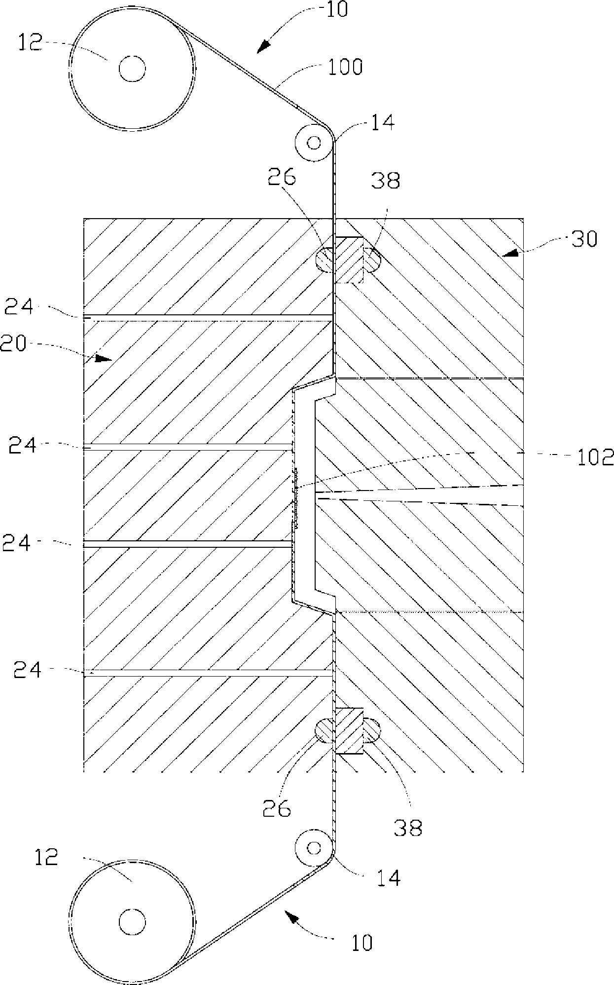
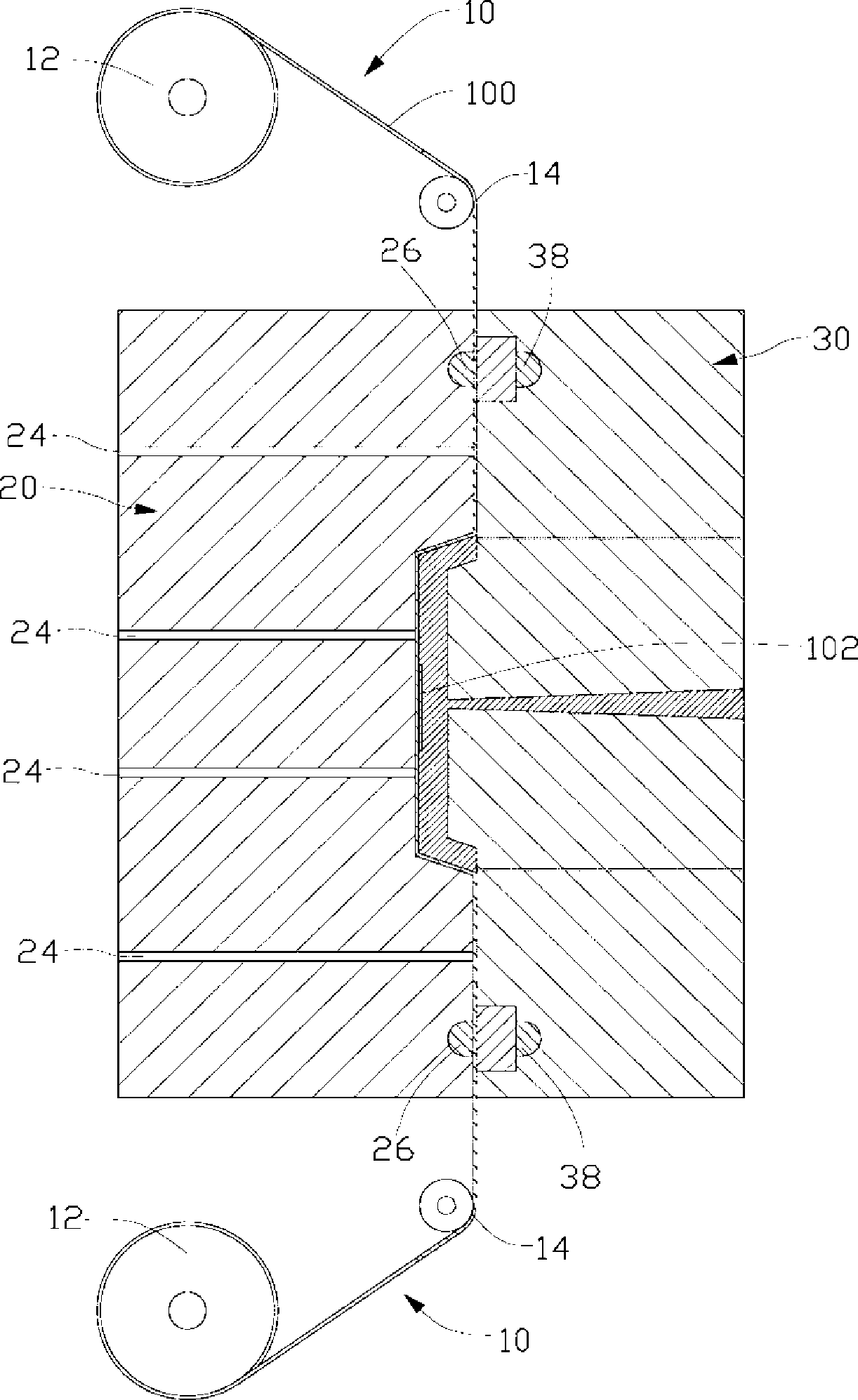
[0016] Such as figure 1 As shown, the molding equipment used for the preferred embodiment of the molding method for implementing the three-dimensional pattern of plastic parts of the present invention includes a film feeding device 10, a die of a female mold 20 and a male mold 30, and a pair of pressing Box 40.

[0017] The mold feeding device 10 includes a pair of film conveying wheels 12 and a pair of guiding wheels 14 . The pair of film conveying wheels 12 are respectively arranged upstream and downstream of the mold for pulling the film 100 . The guide wheels 14 are used to guide the conveying direction of the film 100 . The film 100 includes a substrate and a transfer layer 102 disposed on the substrate. The substrate is generally made of polymer materials such as polycarbonate (PC) and polybutylene terephthalate (PBT). The transfer layer 102 is printed with a three-dimensional ink layer or engraved with a three-dimensional pattern on the side away from the substrate. ...


PUM


Abstract

The invention provides a forming method of solid patterns of a plastic-rubber part, comprising the steps as follows: a die used for decoration forming in the die is provided; the die is provided with a cavity; a film is provided; the film is provided with a transfer printing layer which is provided with patterns with third dimension; the transfer printing layer is jointed to the position corresponding to the cavity of the die; a forming part is formed by injecting rubber into the cavity of the die; and die-opening is carried out so as to lead the transfer printing layer to be jointed on the surface of the forming part and form the plastic rubber part with third-dimension patterns. The forming method of the solid patterns of the plastic-rubber part is provided with the patterns with third dimension on the transfer printing layer of the film, is finally formed by rubber injection, leads the transfer printing layer to be jointed on the surface of the forming part, and forms the plastic-rubber part with smooth appearance and internal third-dimension patterns. The obtained plastic-rubber part with third-dimension pattern has firm coloring and is not easy to be abraded.

Description

technical field [0001] The invention relates to a molding method for forming a three-dimensional pattern on a plastic part. Background technique [0002] Plastic parts are widely used because of their lightness and durability. In order to remind, explain or decorate, it is often necessary to print patterns on plastic parts. Adapt to such a demand, a higher degree of automation in-mold transfer (In MoldRoller, IMR) technology is adopted. The process of in-mold transfer printing technology is: first print the pattern to be printed on the film, so as to form a patterned ink layer on the film; use the film feeding machine to fit the film to the cavity of the mold, And carry out injection molding; after injection molding, the ink layer with patterns is separated from the film. After the film is peeled off, a plastic part with patterns printed on it is obtained. [0003] However, the use of in-mold transfer printing technology can only form flat patterns on plastic parts, but ...

Claims


Application Information

Patent Timeline
Patent Type & Authority Applications(China)
IPC IPC(8): B29C45/14B29C45/17B29C45/26B29C45/34B29B11/00
CPCB29C45/14827B29C45/14688B29C2045/14713B29C2045/14704
Inventor 张浚元
Owner KANGZHUN ELECTRONICS TECH KUNSHAN
Why Eureka
Try Eureka