Long distance concentrated phase conveying system and method with auxiliary blowing apparatus

A conveying system and long-distance technology, which is applied in the direction of conveyors, conveying bulk materials, transportation and packaging, etc., can solve the problems of poor pipeline wear, high alumina damage rate, pipeline wear, etc., and achieve the convenience of crossing roads or buildings Objects, small footprint, and the effect of reducing wear and tear

Inactive Publication Date: 2009-03-25
XIUYAN SHUNDA PNEUMATIC TRANSMISSION EQUIP MANUFACTORY
View PDF0 Cites 29 Cited by
  • Summary
  • Abstract
  • Description
  • Claims
  • Application Information

AI Technical Summary

Problems solved by technology

[0002] At present, the pneumatic conveying for fine powder is divided into dilute-phase pneumatic conveying and dense-phase pneumatic conveying. The two kinds of pneumatic conveying are commonly used in electrolytic aluminum plants for alumina conveying. Dilute-phase pneumatic conveying has low investment and simple operation and control. It is widely used, but the solid-gas ratio is low, the energy consumption is high, the wear and tear on the pipeline is serious, and the alumina damage rate is high; the dense-phase pneumatic conveying, the solid-gas ratio is higher than the dilute phase, the energy consumption is relatively small, and the pipeline wears Poor, the damage rate of alumina is low, dense phase pneumatic conveying gradually replaces dilute phase pneumatic conveying, but it is limited to short-distance feeding, requires a sufficiently high space layout, and has its limitations

Method used


Image

  • Long distance concentrated phase conveying system and method with auxiliary blowing apparatus
  • Long distance concentrated phase conveying system and method with auxiliary blowing apparatus

Examples


Embodiment

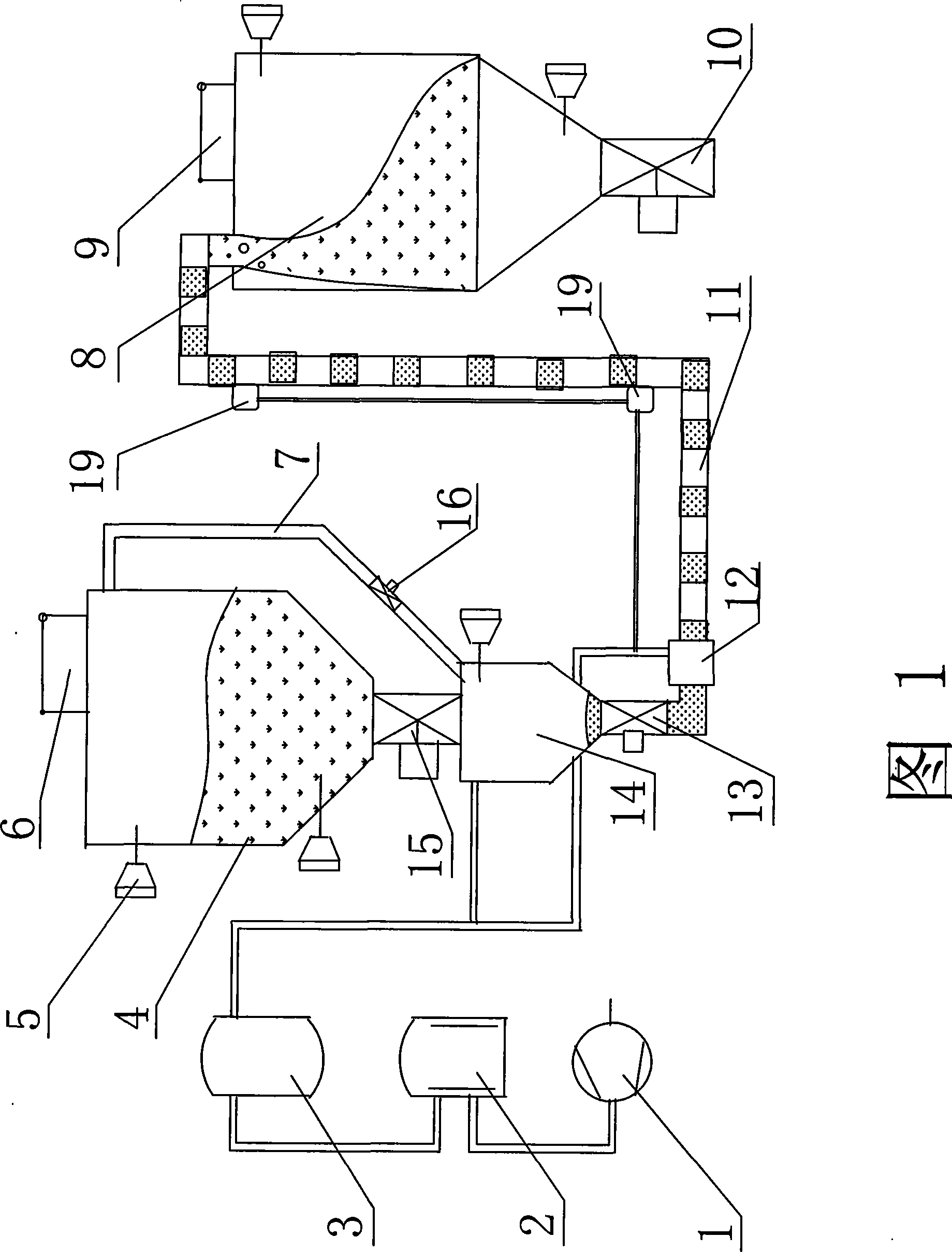
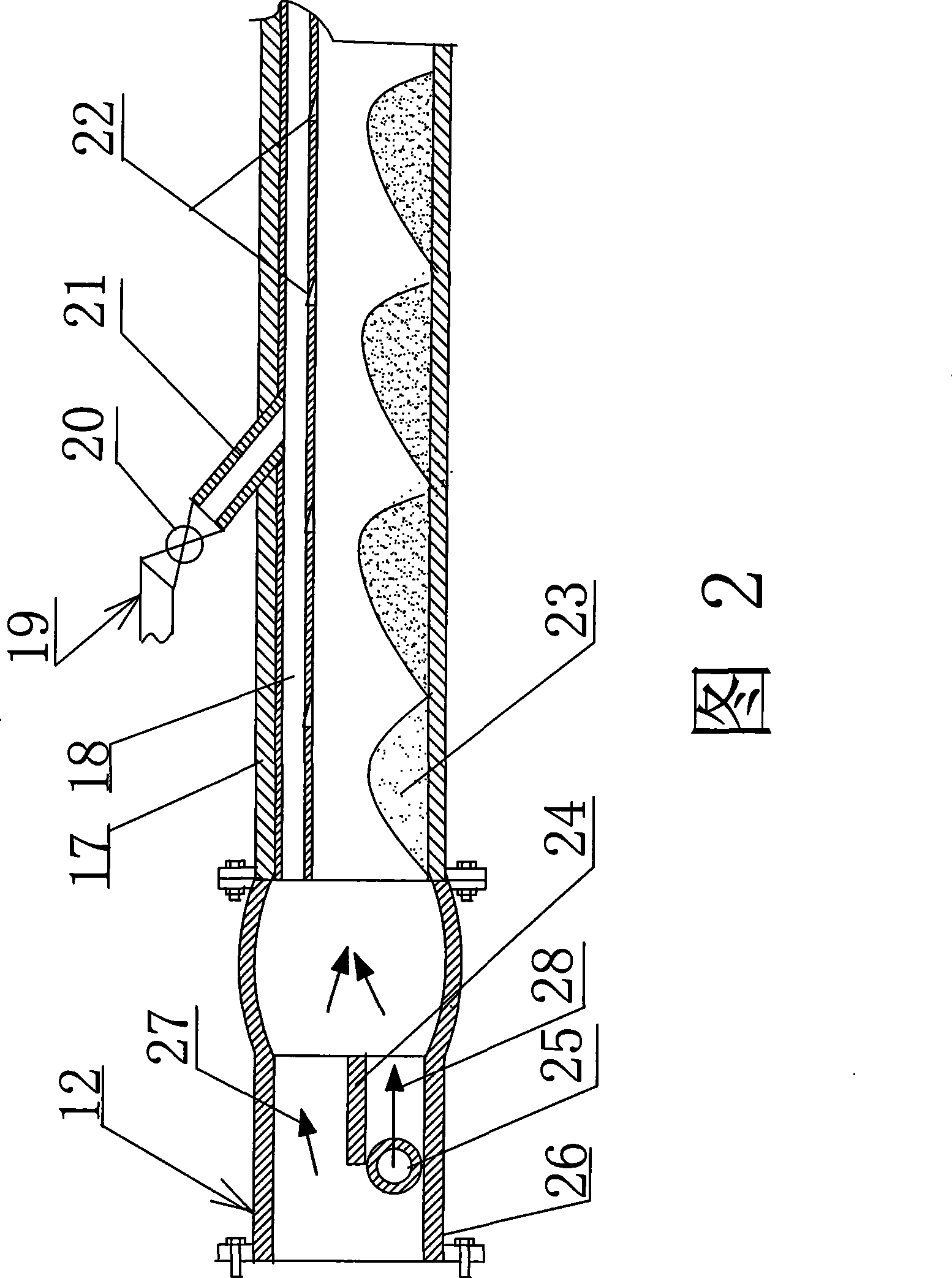
[0024] This example is a long-distance dense-phase conveying system with blowing aid for alumina transportation, including air control device, storage bin 4, sending tank 14, fluidized conveyor 12, online branch silo 8 and dense-phase conveying pipeline 11. The dense phase conveying pipeline 11 is composed of a conveying outer pipe 17, an inner lining pipe 18 and a blowing aid device 19. One side of the inner lining pipe 18 is provided with an air blowing port 22 in sections, and the inner lining pipe 18 is inserted into the conveying outer pipe 17. The liner pipe 18 is fixedly connected to the inner upper wall of the delivery outer pipe 17 with the air blowing port 22 opposite the other side, and the auxiliary blowing device 19 is composed of an inclined nozzle 21 and a control valve 20. The sections are welded on the delivery outer pipe 17 and the inner liner 18, and the inclined nozzle 21 communicates with the inner liner 18. Described fluidization conveyer 12 is made of s...


PUM


Abstract

The invention relates to a long-distance dense-phase conveying system provided with an assistant blowing device and a method thereof. The conveying system comprises an air control apparatus formed by an air compressor, an air storage tank and a system control apparatus; a material storage bin and an on-line sub-bin which are formed by a material tank, a bin controller and a solid-air separator; a sending tank; a fluidization conveyor formed by a streamline casing, a guiding clapboard and an air inlet; a tube liner provided with air inlets arranged by an outer conveying pipe according to subsections and a dense-phase conveying pipeline formed by the assistant blowing device . The tube liner is fixedly connected with the inner upper wall of the outer conveying pipe; the assistant blowing device is fixedly connected and communicated with the outer pipe and tube liner. The dense-phase conveying method comprising the following steps: materials enters the sending tank from the material storage bin and then enters the dense-phase conveying pipeline through the fluidization conveyor and under the effect of compressed air to form a series of material plugs flowing in the conveying pipeline and finally the material reaches the sub-bin for processing and manufacturing. The invention has the advantages that the energy cost is low; the damage to material during the conveying process is less; the wearing to pipeline can be reduced; and the service life is long.

Description

technical field [0001] The invention relates to pneumatic conveying equipment, in particular to a long-distance dense-phase conveying system and method with a blowing aid device. Background technique [0002] At present, the pneumatic conveying for fine powder is divided into dilute-phase pneumatic conveying and dense-phase pneumatic conveying. The two kinds of pneumatic conveying are commonly used in electrolytic aluminum plants for alumina conveying. Dilute-phase pneumatic conveying has low investment and simple operation and control. It is widely used, but the solid-gas ratio is low, the energy consumption is high, the wear and tear on the pipeline is serious, and the alumina damage rate is high; the dense-phase pneumatic conveying, the solid-gas ratio is higher than the dilute phase, the energy consumption is relatively small, and the pipeline wears Poor, low alumina breakage rate, dense-phase pneumatic conveying gradually replaces dilute-phase pneumatic conveying, but i...

Claims


Application Information

Patent Timeline
Patent Type & Authority Applications(China)
IPC IPC(8): B65G53/16B65G53/66
Inventor 张明恩
Owner XIUYAN SHUNDA PNEUMATIC TRANSMISSION EQUIP MANUFACTORY
Why Eureka
Try Eureka