Mechanical energy storage battery

An energy storage battery, mechanical technology, applied in the direction of controlling mechanical energy, mechanical equipment, electromechanical devices, etc., can solve the problems of chemical battery pollution, no practical value, consumption, etc.

Inactive Publication Date: 2009-03-25
游图明
View PDF0 Cites 8 Cited by
  • Summary
  • Abstract
  • Description
  • Claims
  • Application Information

AI Technical Summary

Problems solved by technology

[0004] The present invention provides a mechanical energy storage battery, the main purpose of which is to overcome the pollution problem of chemical batteries, and also to overcome th...

Method used


Image

  • Mechanical energy storage battery
  • Mechanical energy storage battery
  • Mechanical energy storage battery

Examples


specific Embodiment 1

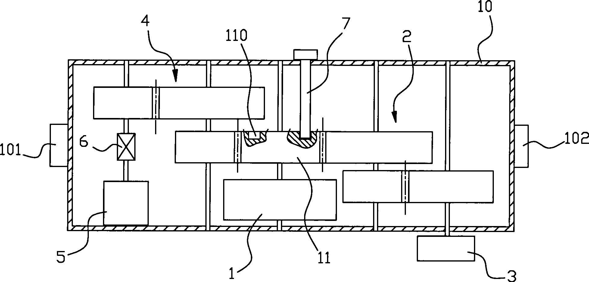
[0018] refer to figure 1 , a mechanical energy storage battery, the main structure includes a spring energy storage device 1 , a deformation drive device 3 , a permanent magnet generator 5 and a casing 10 . The spring energy storage device 1 includes a spring that can store mechanical energy through deformation. The spring has a deformation-driven release end 11. The deformation-driven release end 11 is used to drive the spring to deform by an external force, and the recovery of the spring deformation is also driven by the deformation. The release end 11 is released. The deformation driving device 3 is connected with the deformation driving release end 11 of the spring of the spring energy storage device 1 through a first transmission device 2 . The rotor of the permanent magnet generator 5 is connected to the deformation drive release end 11 of the spring of the above-mentioned spring energy storage device 1 through a second transmission device 4, and its electric output end...

specific Embodiment 2

[0024] The structure of this embodiment is basically the same as that of Embodiment 1, the main difference is that the deformation driving device 3 is a slider slidingly arranged on the housing 10, the first transmission device 2 is a rack and pinion rotating device, The slider is connected with the rack of the first transmission device 2 . That is to say, an external force acts on the slider to make it move in a straight line, which is converted into rotation of the spring in the spring energy storage device 1 through the rack and pinion transmission. On the contrary, during the spring reset process in the spring energy storage device 1 , the slider will be driven to move linearly in the opposite direction.

specific Embodiment 3

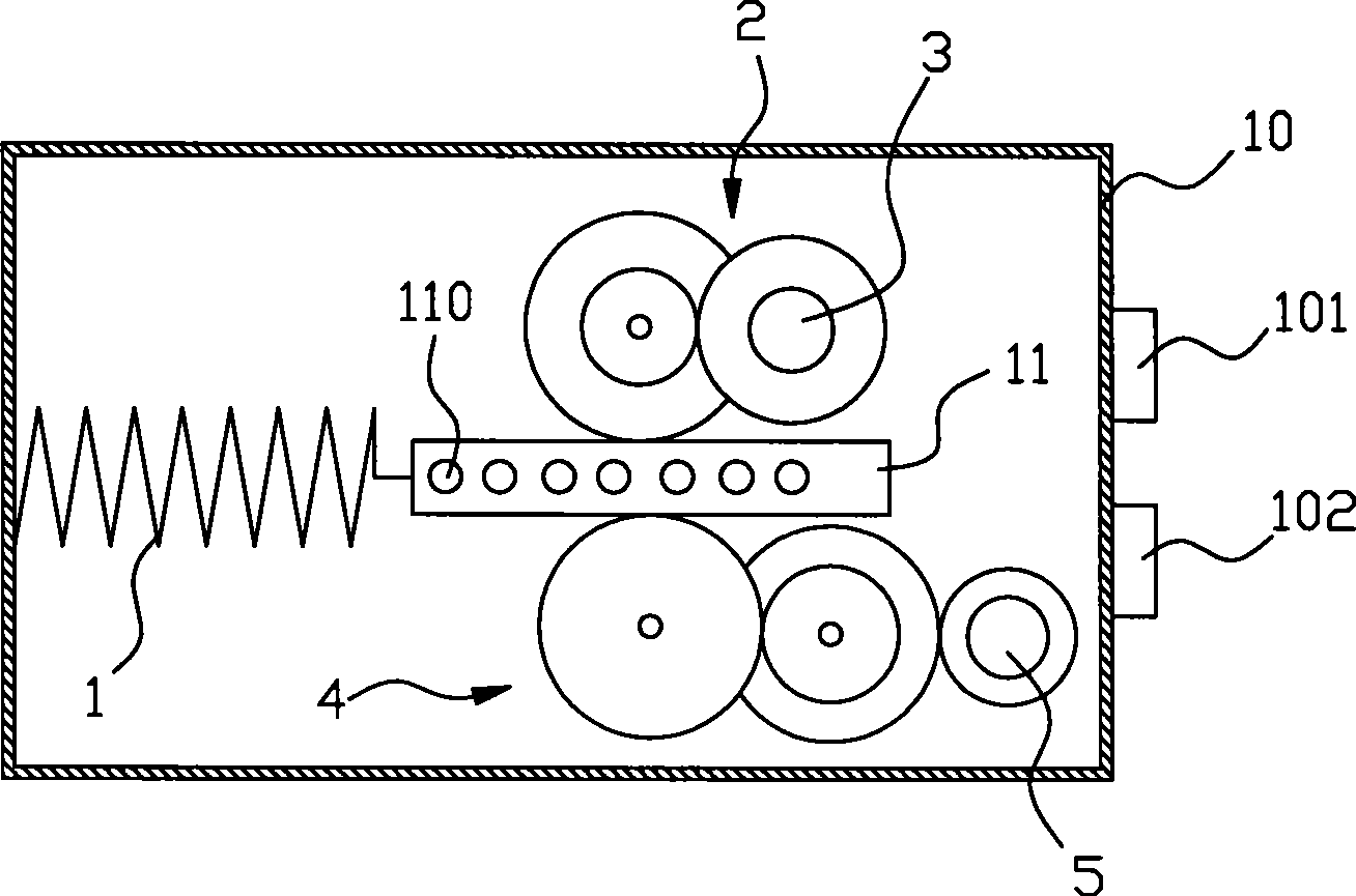
[0025] refer to figure 2 , a mechanical energy storage battery, the main structure includes a spring energy storage device 1 , a deformation drive device 3 , a permanent magnet generator 5 and a casing 10 . The spring energy storage device 1 includes a spring that can store mechanical energy through deformation. The spring has a deformation-driven release end 11. The deformation-driven release end 11 is used to drive the spring to deform by an external force, and the recovery of the spring deformation is also driven by the deformation. The release end 11 is released. The deformation driving device 3 is connected with the deformation driving release end 11 of the spring of the spring energy storage device 1 through a first transmission device 2 . The rotor of the permanent magnet generator 5 is connected to the deformation drive release end 11 of the spring of the above-mentioned spring energy storage device 1 through a second transmission device 4, and its electric output en...


PUM


Abstract

The invention relates to a mechanical type energy storage battery, which comprises a spring energy storage device, a deformation driving device, a permanent magnetic generator and a shell, wherein the spring energy storage device comprises a spring which can store mechanical energy through deformation; the spring is provided with a deformation driving release end; the deformation driving device is connected with the deformation driving release end of the spring through a first transmission device; a rotor of the permanent magnetic generator is connected with the deformation driving release end of the spring through a second transmission device; the electricity output ends of the permanent magnetic generator form the anode and cathode of the mechanical type energy storage battery; the deformation driving release end of the spring is provided with a braking device; and each part of the battery is assembled into a whole through the shell. The deformation driving release end of the spring in the spring energy storage device is provided with the braking device; and the braking device can prevent the resetting action of the spring in the process of restoring deformation at any time, thereby achieving the aim that the mechanical energy stored by once deformation of the spring is used for many times; and the braking device provides a switch for the battery correspondingly so that the battery has practical value.

Description


Claims


Application Information

Patent Timeline
IPC IPC(8): F03G1/00F03G1/02H02K7/18
CPCH02J7/32F03G1/02F21L13/06H02J15/00H02J15/007
Inventor 游图明
Owner 游图明
Why Eureka
Try Eureka