Antenna design method expanding reading scope of low frequency and high frequency RFID system

A design method and antenna technology, which can be applied to antennas, transmission systems, loop antennas, etc., can solve the problems of small antenna working area and increase the cost of readers to read labels, and achieve the effect of improving electromagnetic field strength, improving efficiency, and expanding working area.

Inactive Publication Date: 2009-03-25
江苏天穗智能科技有限公司
View PDF0 Cites 21 Cited by
  • Summary
  • Abstract
  • Description
  • Claims
  • Application Information

AI Technical Summary

Problems solved by technology

In the usual RFID system, the working area of ​​the antenna is too small due to the small output current of the reader (the output current of the reader is limited), and more RFID readers or additional coordination are required to identify items stored in a larger space. The control circuit (called antenna combiner) for multiple antennas increases the time for the reader to read the tag and the cost of building the system

Method used


Image

  • Antenna design method expanding reading scope of low frequency and high frequency RFID system
  • Antenna design method expanding reading scope of low frequency and high frequency RFID system
  • Antenna design method expanding reading scope of low frequency and high frequency RFID system

Examples


Embodiment Construction

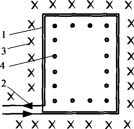
[0012] Below in conjunction with accompanying drawing and example the method of the present invention is further described.

[0013] see figure 1 , the length of the conductor winding the small rectangular antenna coil 1 is calculated according to the inductance value range of the antenna in the working frequency band of the reader and the material and diameter of the conductor. This length is only an estimated length and can be increased or decreased; the small rectangular The side length of the coil 1 is determined according to the coverage area, the number of turns of the coil and the center of the antenna coil 1 without a reading blind area. If the direction drawn in the figure is the direction 2 of current flow, then when the small rectangular antenna coil 1 has a current flowing through it, the direction of the electromagnetic field generated is away from the paper surface 3 outside the small rectangle, and passes through the inside of the small rectangle. Out of paper ...


PUM


Abstract

The invention discloses a method for designing an antenna which can enlarge the reading range of a low frequency or high frequency RFID system. A plurality of pairs of space-separated reader antennas are connected through a multi-antenna search-read interface circuit. The method is characterized in that the coils of each pair of reader antenna are composed of a plurality of small coils connected in a manner of combining parallel connection with series connection; the current directions of adjacent edges of adjacent small coils are opposite; an impedance matching circuit is capacitive and resonates on the work frequency of the reader with inductive antenna coils. The small coils can be produced into shapes of a triangle, a rectangle, a square, a circle, an oval and a polygon, and a plurality of small coils match with the shape of the antennas after the combination of the parallel connection and the series connection according to the shapes of the areas the antenna needs to cover.

Description

technical field [0001] The invention relates to an RFID system reader antenna, in particular to an antenna design method for expanding the reading range of a low-frequency or high-frequency RFID system, which is suitable for identifying items stored in a large space using a low-frequency or high-frequency RFID system. In the case of low current operation, the working area of ​​the RFID reader is enlarged and there is no reading blind area in the central area of ​​the reader antenna coil. Background technique [0002] A typical radio frequency identification RFID system includes an RFID tag (also called an electronic tag, a transponder), an RFID reader (also called a reader, a reading head), and a main system data processing unit (usually a computer (PC)). The RFID reader sends a radio frequency signal of a certain frequency to generate an electromagnetic field around the antenna coil (antenna working area). If the RFID tag is in the electromagnetic field generated by the RFI...

Claims


Application Information

Patent Timeline
Patent Type & Authority Applications(China)
IPC IPC(8): H01Q7/00G06K19/077G06K7/00H04B5/00
Inventor 王刚王洪金刘小琴杨波赵文婧
Owner 江苏天穗智能科技有限公司
Why Eureka
Try Eureka