Linear drive and linear compressor with adaptable output

A linear drive, linear compressor technology, applied in the direction of the engine without a rotating main shaft, the engine element, the variable capacity engine, etc., can solve the problems of increasing the required parts and spare parts spectrum, high cost, complex design, etc. The effect of efficient and reliable operation

Inactive Publication Date: 2009-03-25
BSH BOSCH & SIEMENS HAUSGERAETE GMBH
View PDF0 Cites 1 Cited by
  • Summary
  • Abstract
  • Description
  • Claims
  • Application Information

AI Technical Summary

Problems solved by technology

This design is complex, costly and significantly increa

Method used


Image

  • Linear drive and linear compressor with adaptable output
  • Linear drive and linear compressor with adaptable output
  • Linear drive and linear compressor with adaptable output

Examples


Embodiment Construction

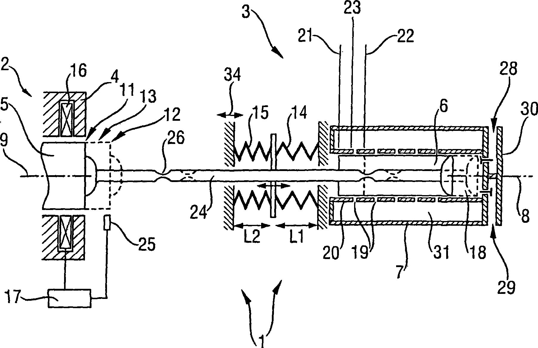
[0056] figure 1 A sectional view of a device 1 according to the invention is shown with a linear drive 2 and a linear compressor 3 . The linear drive 2 has a stator 4 , wherein a rotor 5 moves in a reciprocating manner along a drive axis 9 . The rotor 5 is driven by means of drive coils 16 which are supplied with drive coil current by means 17 for actuating the drive coils 16 .

[0057] The rotor 5 oscillates between a first rotor reversal point 11 and a second rotor reversal point 12 and in doing so passes through a rotor zero position 13 . The movement of the rotor 5 is sensed by means of a position sensor 25 which transmits position information to the means 17 for actuating the drive coils 16 , as a result of which a control system is implemented for the movement of the rotor 5 as a whole.

[0058] The linear compressor 3 has a piston housing 7 in which the compressor piston 6 oscillates in a reciprocating manner along the piston axis 8 between a first piston reversing po...


PUM

PropertyMeasurementUnit
Lengthaaaaaaaaaa

Abstract

The invention relates to an apparatus (1) comprising a linear drive (2) which has a stator (4) and a rotor (5) movable in a reciprocating manner therein along a drive axis (9) between a first (11) and a second (12) rotor reversal point about a rotor zero position (13), and/or comprising a linear compressor (3) which has a piston housing (7) and a compressor piston (6) which is movable in a reciprocating manner therein along a piston axis (8) and a first (21) and a second (22) piston reversal point about a piston zero position (23) and can be driven by the linear drive (2), wherein either the rotor zero position (13) or the piston zero position (23) is adjustable and/or at least one spring element (14, 15) acts on the rotor (5) or on the compressor piston (6), the length of which can be varied, in particular shortened, and/or the spring constant of which can be changed, in particular increased; and a method for cooling commodities (27) or for compressing a fluid (18). The invention is distinguished by the fact that adaptation of the output delivered by the apparatus has no substantial effect on the electromechanical efficiency of the apparatus, as a result of which a linear drive (2) and a linear compressor (3) can be constructed in an especially cost-effective manner, since the diversity of the products can be considerably reduced.

Description


Claims


Application Information

Patent Timeline
Owner BSH BOSCH & SIEMENS HAUSGERAETE GMBH
Why Eureka
Try Eureka