Switching device

A switchgear and switch technology, applied to protection switches, protection switch parts, protection switch distinguishing marks, etc., can solve the problems of slow and long delays, and achieve the effects of simplified manufacturing, simple cost, and production waste avoidance

Inactive Publication Date: 2009-03-25
MOELLER GEBAUDEAUTOMATION KG
View PDF5 Cites 4 Cited by
  • Summary
  • Abstract
  • Description
  • Claims
  • Application Information

AI Technical Summary

Problems solved by technology

Through the complex and time-consuming manufacture of the housing, it is only possible to r

Method used


Image

  • Switching device
  • Switching device
  • Switching device

Examples


Embodiment Construction

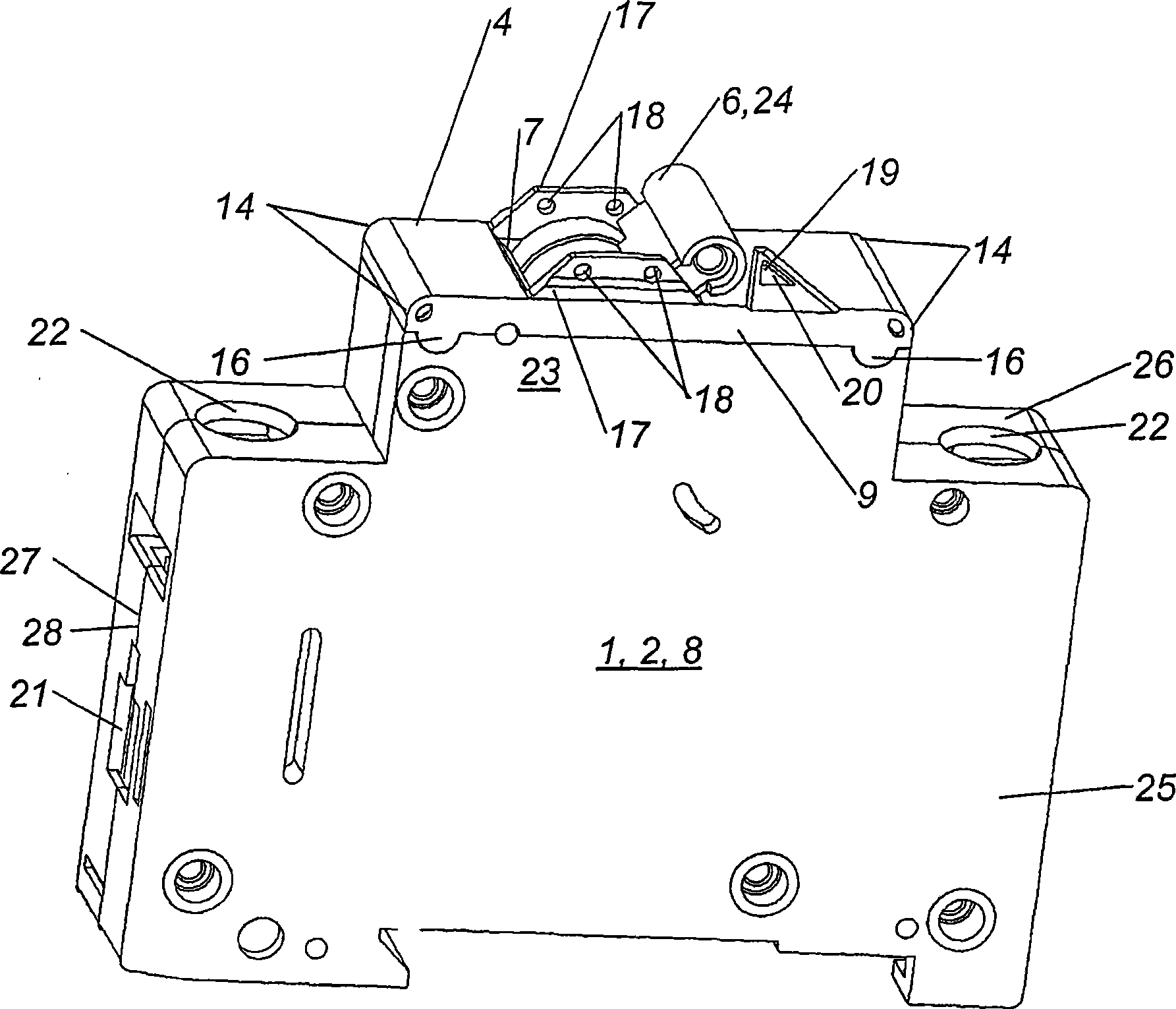
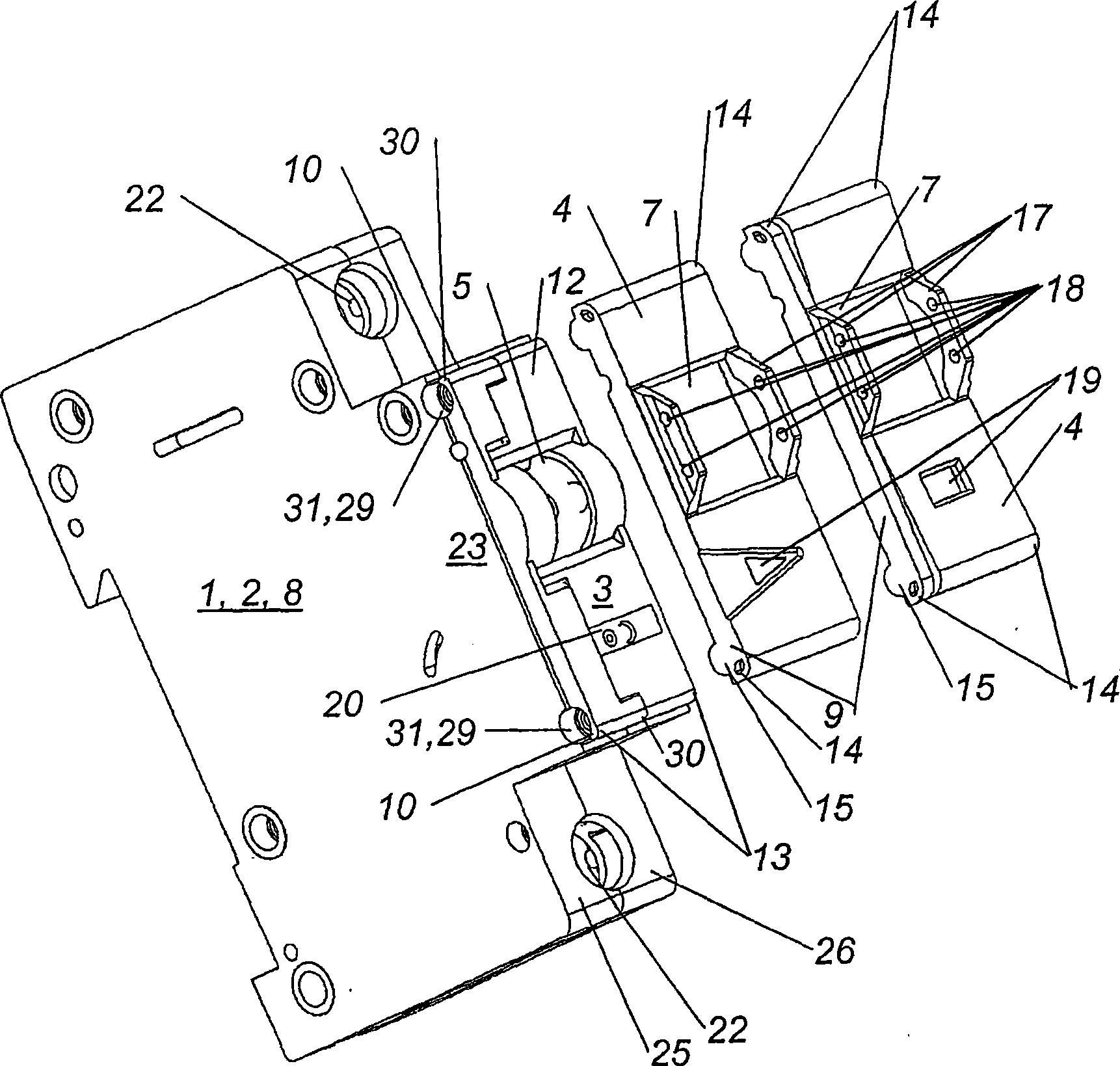
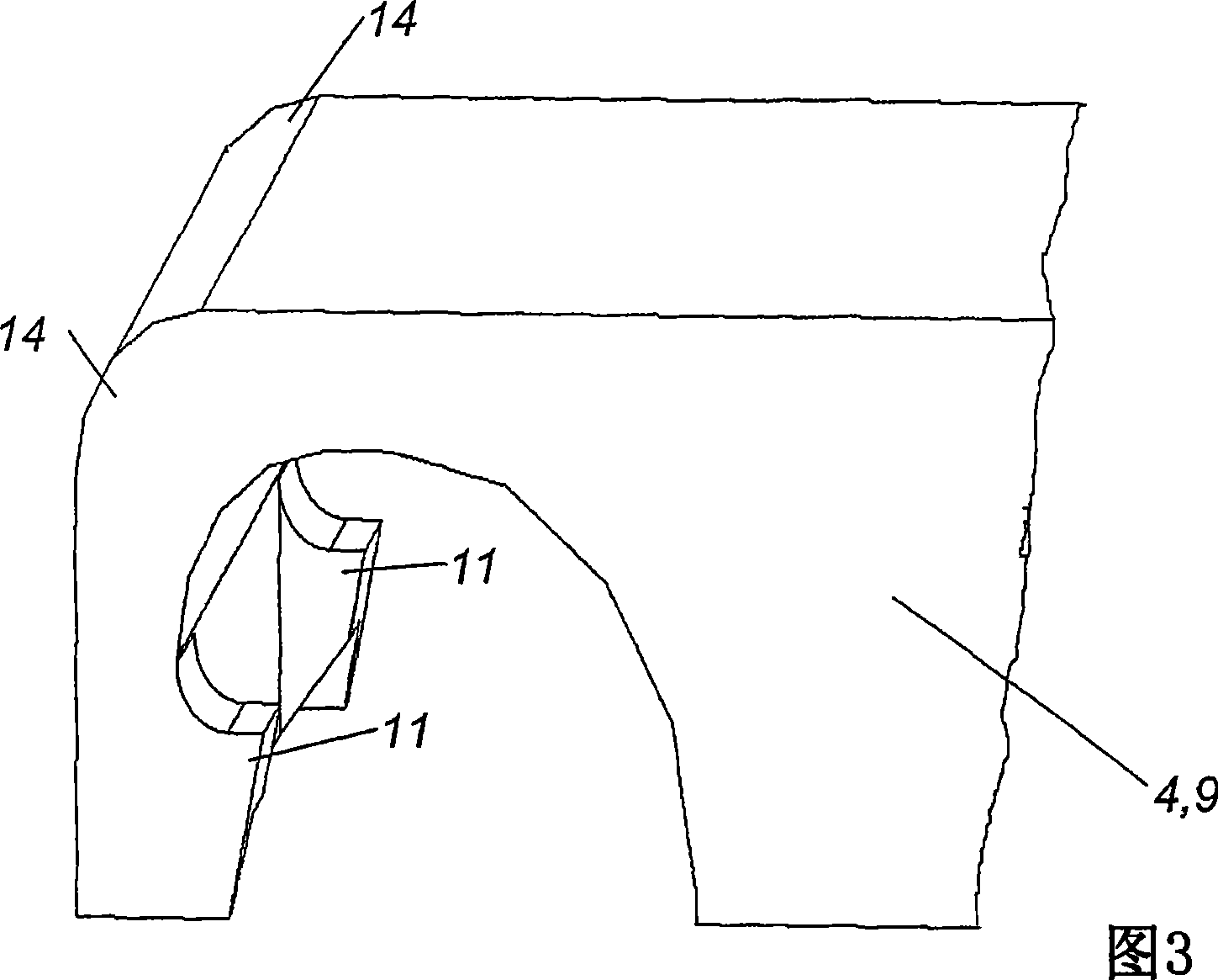
[0031] figure 1 and Figure 6 A particularly preferred embodiment of a switching device 1 with a housing 2 and switching contacts for closing and / or opening at least one current circuit is shown, wherein a triggering device for automatically separating the switching contacts is provided, Furthermore, the housing 2 has at least one front side 3 , wherein a cover 4 is clipped onto the front side 3 .

[0032] The switchgear 1 according to the invention can be every type of switchgear 1 . The switching device 1 is preferably designed for electrical protective measures, in particular a circuit breaker and / or a fault current breaker.

[0033] Through the measures according to the invention, the switchgear 1 can be produced in a simple and cost-effective manner, wherein it is possible to react quickly and flexibly to changing requirements due to the market or customers. As a result, the switching device 1 can be produced with the same functionality for all markets, countries and / o...


PUM


Abstract

The device (1) has switching contacts that close and/or open an electric circuit. A tripping apparatus is provided for automatically disconnecting the switching contacts, and a housing (2) has a front side, onto which a cover cap (4) is clipped. The cover cap has a latch engaged into a locking groove that is arranged at the housing. The housing has a housing projection that forms the front side.

Description

technical field [0001] The invention relates to a switching device, in particular a circuit breaker and / or a fault current breaker, with a housing and with switching contacts for closing and / or opening at least one current circuit, wherein an automatic disconnecting switch is provided Triggering device for contacts, wherein the housing has at least one front face. Background technique [0002] Switching devices, in particular protective switches, such as line circuit breakers and / or fault current circuit breakers, are known, which are sold and used essentially with the same function in many countries around the world. This switchgear has exactly the same internal construction in different countries. However, local rules regarding the mandatory marking of switchgear differ in many countries. This may, for example, be necessary in country A in the form of an embossed marking on the switchgear, whereas in country B other markings are required which, for example, are not embos...

Claims


Application Information

Patent Timeline
IPC IPC(8): H01H71/02H01H71/06
CPCH01H2071/0242H01H71/025H01H71/0264
Inventor 恩斯特·哈默迈尔
Owner MOELLER GEBAUDEAUTOMATION KG
Why Eureka
Try Eureka