Channel connectivity diagnostic equipment of probe-head control module of ultrasonic diagnostic device

A technology of ultrasonic diagnostic instrument and control module, which is applied in ultrasonic/sonic/infrasonic diagnosis, sonic diagnosis, infrasonic diagnosis, etc. It can solve problems such as inability to accurately judge whether there is a fault in the probe control module channel, so as to improve production test efficiency and save energy. The effect of testing costs

Inactive Publication Date: 2009-04-01
SHENZHEN LANDWIND IND
View PDF0 Cites 3 Cited by
  • Summary
  • Abstract
  • Description
  • Claims
  • Application Information

AI Technical Summary

Problems solved by technology

[0004] The technical problem to be solved by the present invention is to provide a diagnostic device for the channel connectivity of the probe control module of an ultrasonic diagnostic instrument, which o

Method used


Image

  • Channel connectivity diagnostic equipment of probe-head control module of ultrasonic diagnostic device
  • Channel connectivity diagnostic equipment of probe-head control module of ultrasonic diagnostic device
  • Channel connectivity diagnostic equipment of probe-head control module of ultrasonic diagnostic device

Examples


Example Embodiment

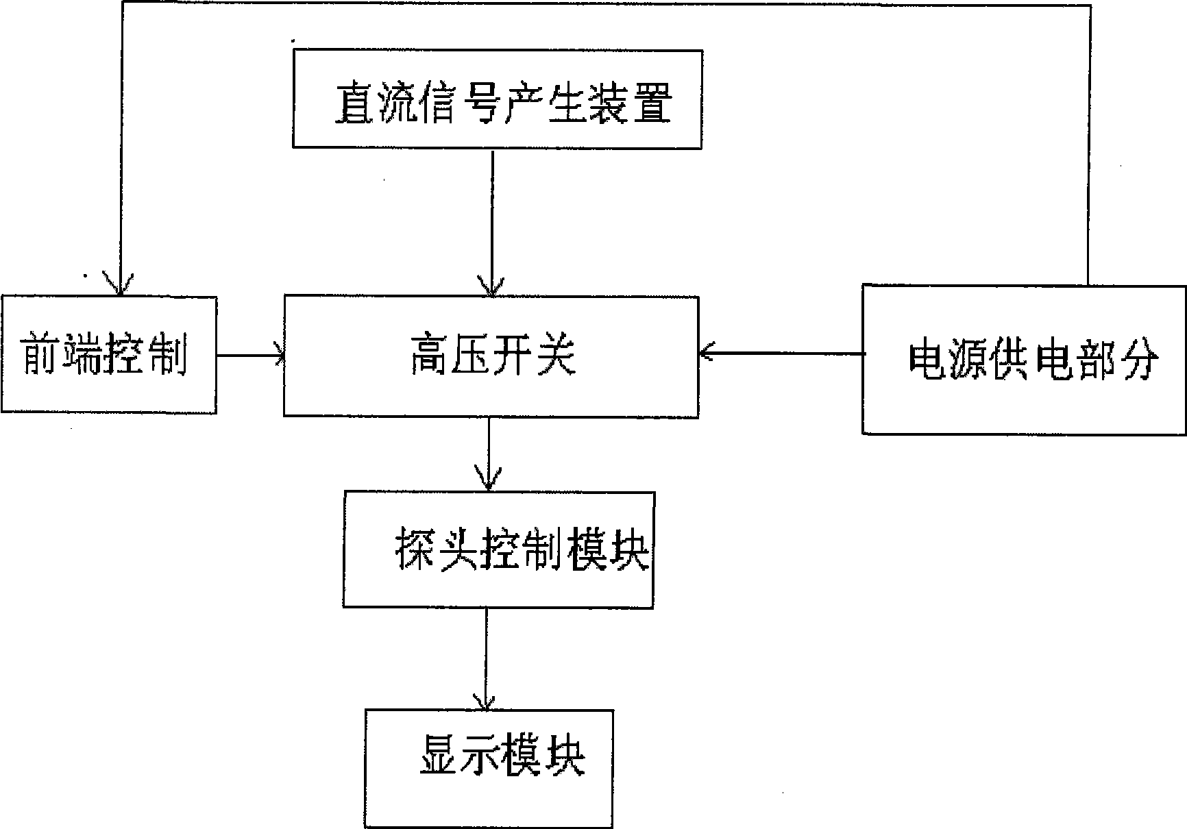
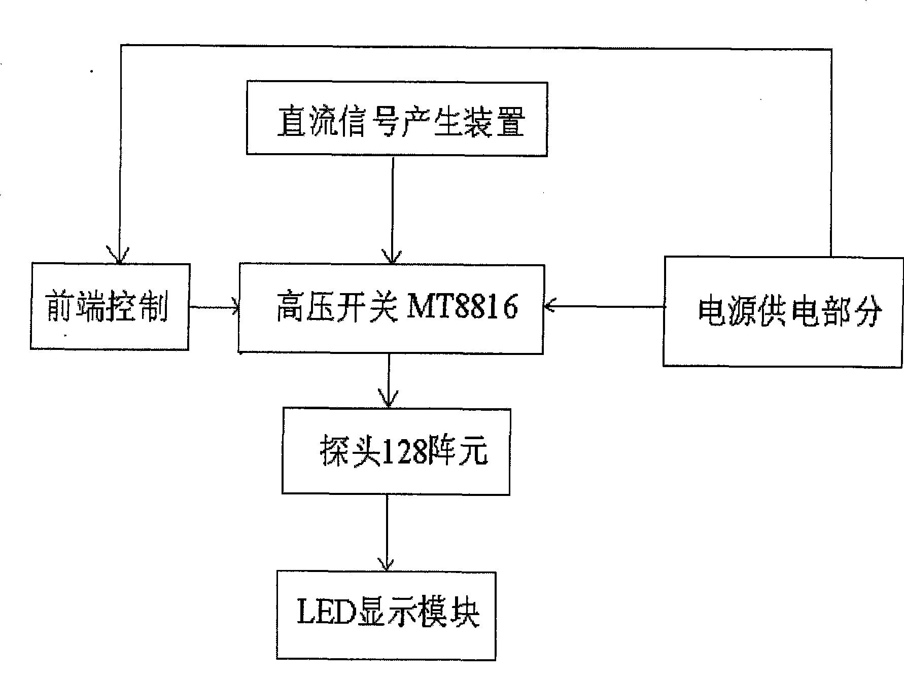
[0022] Below according to accompanying drawing and embodiment the present invention will be described in further detail:

[0023] like figure 2 , image 3 , Figure 4 , Figure 5 and Image 6 As shown, the ultrasonic diagnostic instrument probe control module channel connectivity diagnostic device of the present invention includes a power supply, a DC signal generator, a high-voltage switch, a front-end control module and a display module, a power supply and a DC signal generator, a high-voltage switch, and a front-end control module. The DC signal generating device and the front-end control module are respectively connected to the high-voltage switch, the high-voltage switch is connected to the input terminal of the probe control module to be tested, and the output terminal of the probe control module to be tested is connected to the display module. The display module can be set to The light-emitting diode display board, the light-emitting diode display board includes lig...


PUM


Abstract

A passage convexity diagnostic device of a probe control module of a diasonograph is characterized in that the device comprises a power supply source, a DC signal generation device, a high voltage switch, a front-end control module and a display module. The power supply source is respectively connected with the DC signal generation device, the high voltage switch, and the front-end control module. The DC signal generation device and the front-end control module are respectively connected with the high voltage switch connected with the input end of the probe control module which needs to be tested; the input end of the probe control module which needs to be tested is connected with the display module.

Description

technical field [0001] The invention relates to the technical field of ultrasonic diagnosis, in particular to a diagnostic device for channel connectivity of a probe control module of an ultrasonic diagnostic instrument. Background technique [0002] As shown in Figure 1, the existing ultrasonic diagnostic equipment is mainly composed of five parts: a probe control module, a receiving module, a transmitting module, a beamformer, and a digital signal processing module. The specific implementation principle is as follows: the pulse sent by the transmitting module is added to the chip of the probe array element, and the ultrasonic pulse sent by the chip propagates in the soft tissue of the human body. When the ultrasonic wave hits the human body tissue, it is reflected, and the reflected echo It is amplified and processed by the receiving module, and the processed signal is uploaded to the computer through the PCI card, and then the image is displayed on the monitor. [0003] ...

Claims


Application Information

Patent Timeline
IPC IPC(8): A61B8/00G01R31/02
Inventor 谢洵张剑英林阳辉
Owner SHENZHEN LANDWIND IND
Why Eureka
Try Eureka