A bag dust collector and its manufacturing method

A technology of bag dust collector and manufacturing method, which is applied in the direction of chemical instruments and methods, separation methods, and separation of dispersed particles, which can solve the problems of insufficient purification effect, increase the frequency of back blowing, and low recovery efficiency, so as to improve the adsorption performance and purification effect, the chance of avoiding direct contact, and the effect of avoiding direct washing

Active Publication Date: 2011-11-30
GUIYANG AL-MG DESIGN & RES INST
View PDF0 Cites 0 Cited by
  • Summary
  • Abstract
  • Description
  • Claims
  • Application Information

AI Technical Summary

Problems solved by technology

Due to the strong scouring force of the dusty gas entering the box at high speed on the windward side of the filter bag, the windward side of the filter bag cannot adhere to dust, and a large amount of dust gathers on the leeward side of the filter bag
This will cause the dust adsorption on the leeward side of the dust collector to be too thick, and the gas cannot pass through, which will inevitably increase the frequency of blowback; on the windward side, due to its good air permeability and strong adsorption force, fine dust particles will directly pass through the filter bag and be discharged into the atmosphere.
As a result, the purification efficiency and dust removal efficiency of the existing bag filter cannot be improved
Among them, the above defects are most obvious in the flue gas dry purification treatment system, because in the flue gas dry purification treatment system, the harmful gases in the flue gas need to be adsorbed and purified by adsorbents, which are generally various types of dust. The adsorbent needs to be recycled. Due to the above reasons, the adsorbent on the filter bag is unevenly distributed. Some harmful gases enter the clean air chamber directly through the filter bag without contacting the adsorbent, which cannot achieve a good purification effect. The air permeability is good, and some small particle adsorbents to be recovered also enter the clean air chamber through the filter bag, and the recovery efficiency is low

Method used


Image

  • A bag dust collector and its manufacturing method
  • A bag dust collector and its manufacturing method
  • A bag dust collector and its manufacturing method

Examples


Embodiment Construction

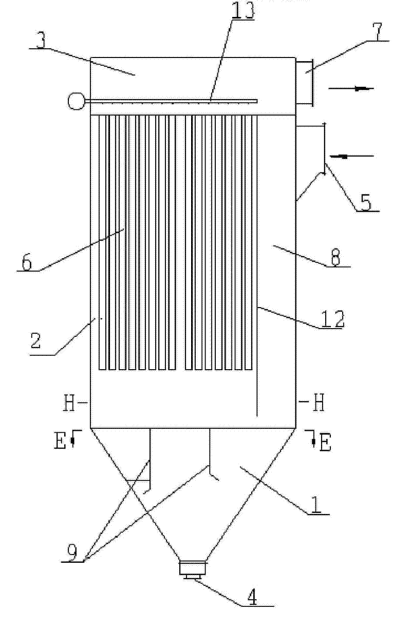
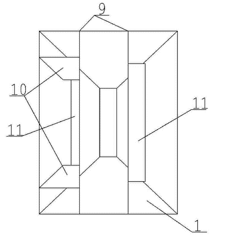
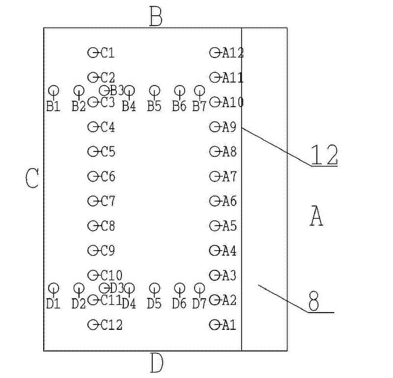
[0027] Embodiments of the present invention: the structure of the present invention is as figure 1 , figure 2 , Figure 4 and Figure 5 As shown, it is composed of an existing bag filter connected with an ash hopper 1, a middle box 2 and an upper box 3 in sequence and is restructured. An ash discharge port 4 is installed at the lower end of the ash hopper 1, and an ash discharge port 4 is installed in the middle box. 2 is connected with an air inlet 5, in which a filter bag 6 is suspended, and a gas outlet 7 and a blowback system 13 are installed on the upper box body 3. When making the present invention, one side in the middle box body 2 An air flow passage 8 communicating with the air inlet 5 is provided, which can be formed by welding a partition 12 parallel to the box panel (side A) connected to the air inlet 5 in the middle box, and welded After the dividing plate 12 is finished, the opening of the air flow passage 8 formed is opposite to the opening of the ash hoppe...


PUM


Abstract

The invention relates to a bag filter and a manufacturing method thereof. It is to set an air flow channel connected with the dust-containing gas inlet of the bag filter on one side of the box body of the existing bag filter, so that the air flow channel The outlet is connected to the ash hopper below the bag filter, and two airflow baffles parallel to each other are set in the ash hopper, and the airflow baffle is parallel to the box panel on the side connected to the air inlet; The dusty gas rushes into the ash hopper under the guidance of the airflow channel, which avoids the direct washing of the dusty gas to the filter bag of the bag filter; In the filter bag area of ​​the box, under the action of negative pressure, the gas passes through the filter bag and is discharged from the upper box, and the dust is evenly adsorbed on the filter bag, and the dust evenly adsorbed on the filter bag can improve the adsorption of the bag filter. Performance and purification effect.

Description

Technical field: [0001] The invention relates to a dust removal device and a manufacturing method thereof, in particular to a novel bag filter and a manufacturing method thereof. technical background: [0002] At present, dust-containing gas is mostly filtered by bag filter. Its working principle is to introduce dust-containing gas into the box of bag filter through connecting pipes, and the dust-containing gas is moved to the filter bag by the gravity of the induced draft fan. The dust is adsorbed on the filter bag, and the purified gas is discharged from the filter bag, so as to achieve the effect of air purification. However, because the gas connecting pipes of the existing bag filter are directly connected to the upper side of the middle box of the bag filter, the flow rate of the dusty gas entering the box will increase under the action of the induced draft fan, and the inertial force Under the action of high speed, it rushes into the box of the bag filter, and part of...

Claims


Application Information

Patent Timeline
Patent Type & Authority Patents(China)
IPC IPC(8): B01D46/02
Inventor 邓翔吕维宁刘讯
Owner GUIYANG AL-MG DESIGN & RES INST
Why Eureka
Try Eureka