Metal barrel flanging device

A metal cylinder and flanging technology, applied in metal processing equipment, forming tools, manufacturing tools, etc., can solve problems such as low yield, low production efficiency, and low product precision

Active Publication Date: 2009-04-01
SHANGYU MINGXIN FANS
View PDF0 Cites 30 Cited by
  • Summary
  • Abstract
  • Description
  • Claims
  • Application Information

AI Technical Summary

Problems solved by technology

The above-mentioned operations have the disadvantages of high labor intensity, low production efficiency, low product precision, and low yield.
Moreover, it is more difficult to deal with some metal cylinders with thicker walls.

Method used


Image

  • Metal barrel flanging device
  • Metal barrel flanging device
  • Metal barrel flanging device

Examples


Embodiment Construction

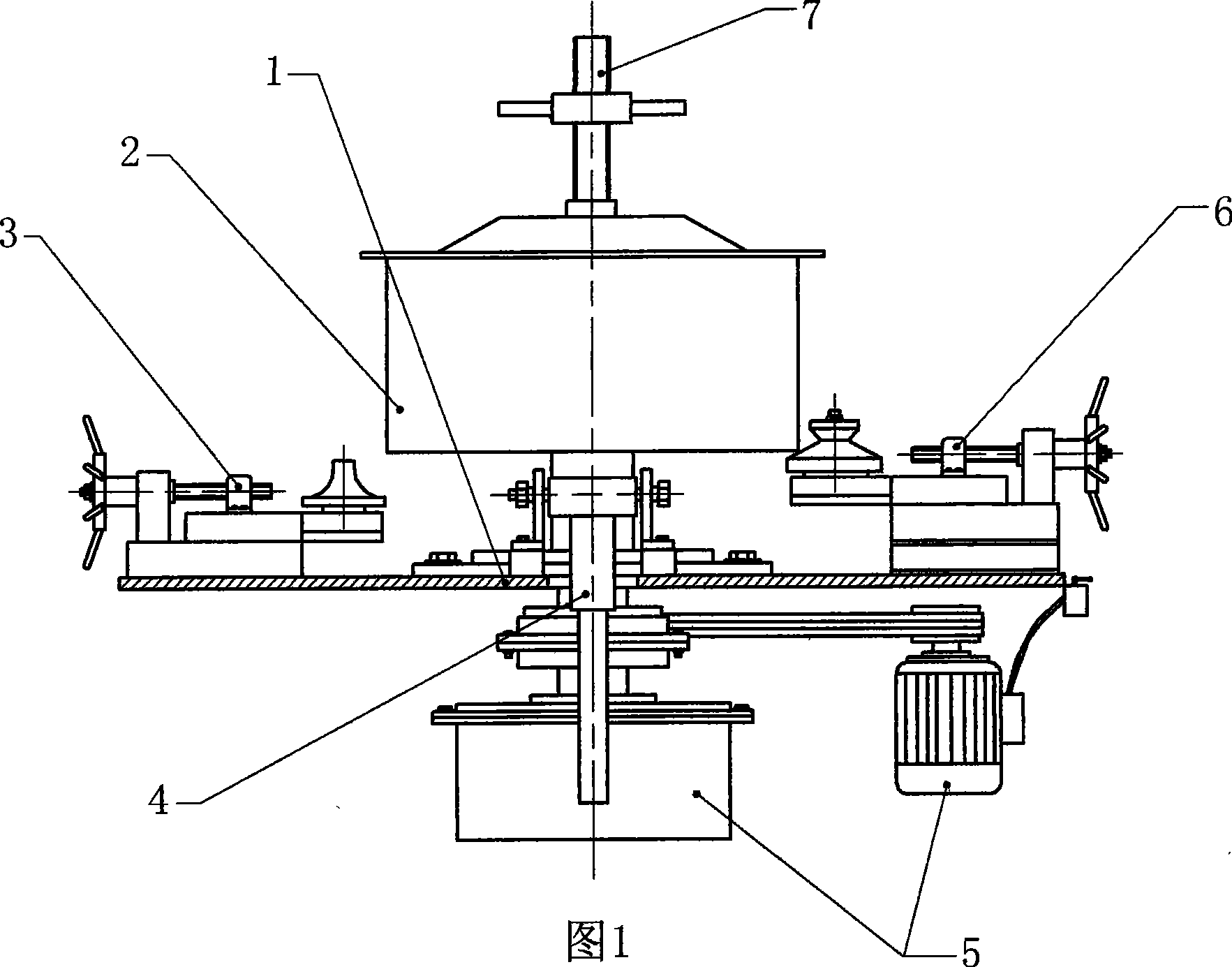
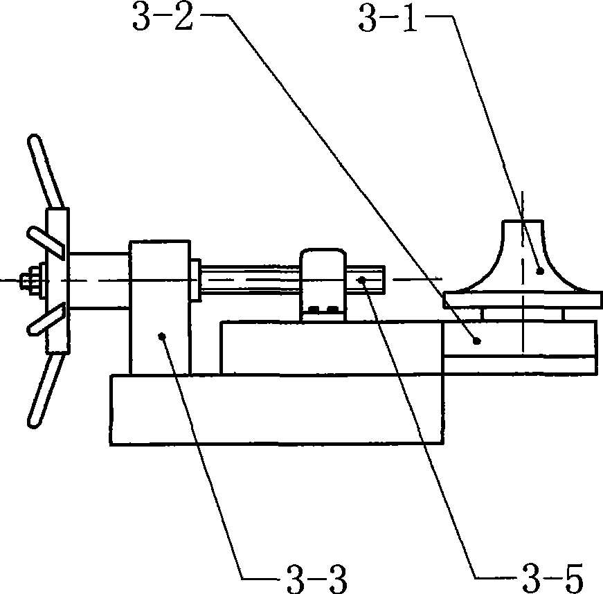
[0021] As shown in FIG. 1 , the metal cylinder flanging equipment of the present invention includes a workbench 1 on which a cylinder positioning assembly 2 , an arc flanging assembly 3 and a driving machine 5 are arranged.

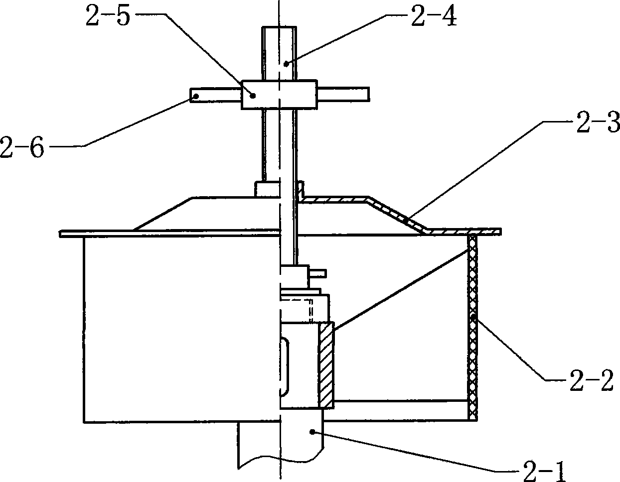
[0022] The cylinder positioning assembly includes a rotating shaft 2-1, a cylindrical support ring mold 2-2, a binder plate 2-3 and a locking and loosening device, the rotating shaft 2-1 is connected to the driving machine 5 through transmission, and the rotating shaft 2- 1 is also fixed with the cylinder support ring mold 2-2, the binder plate 2-3 is above the cylinder support ring mold 2-2, and a locking device is provided on the positioning plate 2-3.

[0023] see figure 2 , the locking device includes a screw rod 2-4, a nut 2-5 threadedly matched with the screw rod 2-4, and one end of the screw rod 2-4 is connected to the rotating shaft 2-1. The screw mandrel 2-4 passes through the pressing plate 2-3, and by relatively rotating the screw mandrel 2-4 ...


PUM


Abstract

The invention discloses metal cylinder flanging equipment, comprising a working platform; the working platform is provided with a cylinder locating component, an arc flanging component and a driver; the cylinder locating component comprises a rotating shaft, a cylinder circle-expanding mold, a swaging tray and a locking device; the rotating shaft is connected with the driver in a transmission way and fixed with the cylinder circle-expanding mold; the swaging tray is arranged above the cylinder circle-expanding mold and provided with the locking device; the arc flanging component comprises a rotating flanging mold which is vertically fixed on the working platform and the section of the flanging mold is round and the two longitudinal sidelines of the mold are hyperbola. In the proposal, the location of a cylinder fixes a metal cylinder and drives the metal cylinder to rotate at the same time; when the metal cylinder rotates, the inside toward the end opening is in contact with the flanging mold and the arc extension of the metal cylinder edge is realized. Therefore, the labor intensity of workers is reduced, and the productivity, the product precision and the yield are promoted.

Description

technical field [0001] The invention relates to a mechanical processing device, in particular to a metal cylinder flanging device. Background technique [0002] Flanging the sides of some metal cylinders can improve the strength of the cylinder and achieve the purpose of saving materials. In addition, the arc flanging structure treatment on the sides of the metal cylinder of the axial flow fan can make it have a streamlined shape. Shape, reduce the resistance of the fluid when the fan is running, and save energy. [0003] The fan manufacturing industry often processes the two ends of the metal cylinder of the axial flow fan. Generally, one end is an arc-shaped structure, similar to the shape of a bell mouth, and the other end is an "L"-shaped flange. Currently, it is processed in the fan manufacturing industry. The equipment used in the above structure includes a fixture and a joystick. The fixture can clamp the metal cylinder to rotate, and one end of the joystick is fixed...

Claims


Application Information

Patent Timeline
Patent Type & Authority Applications(China)
IPC IPC(8): B21D19/00B21D19/12B21D37/10
Inventor 董明祥吴兴海
Owner SHANGYU MINGXIN FANS
Why Eureka
Try Eureka