Hydrodynamic auxiliary shoring cutter-holder and shoring method

A technology of hydrodynamic pressure and auxiliary support, applied in the direction of reamer, boring bar, tool holder accessories, etc., can solve the problem of high installation and adjustment requirements of support bars or support blocks, unsatisfactory support effect, and high manufacturing and use costs. problem, to achieve good effect of absorbing tool vibration, increasing rigidity and good effect

Inactive Publication Date: 2009-04-01
HEFEI UNIV OF TECH
View PDF0 Cites 7 Cited by
  • Summary
  • Abstract
  • Description
  • Claims
  • Application Information

AI Technical Summary

Problems solved by technology

However, for the tool bar structure with auxiliary support of support bars or support blocks, in actual operation, the installation and adjustment requirements for support bars or support blocks are relatively high, and the manufacturing and use costs are high; For the normal machining, it is necessary to require that the support bar is slightly lower than the height of the tool tip in the radial direction. Therefore, there is still a gap between the support bar and the boring hole. This gap makes the boring tool bar or reamer tool bar Still bends and vibrates, not ideally supported

Method used


Image

  • Hydrodynamic auxiliary shoring cutter-holder and shoring method
  • Hydrodynamic auxiliary shoring cutter-holder and shoring method

Examples


Embodiment Construction

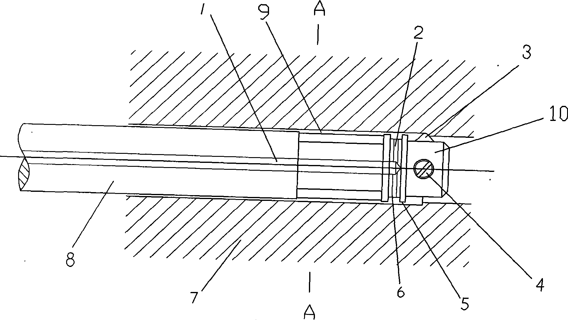
[0014] see figure 1 In this embodiment, the hydrodynamic auxiliary support tool bar has a bar head 10 for installing a tool, a hosel for arranging the cutting fluid flow channel 2, and a shaft 8 as a support for the bar head, and the central axial hole of the shaft 8 is set It is the cutting fluid supply channel 1, and the liquid supply channel 1 is connected with the hosel cutting fluid flow channel 2.

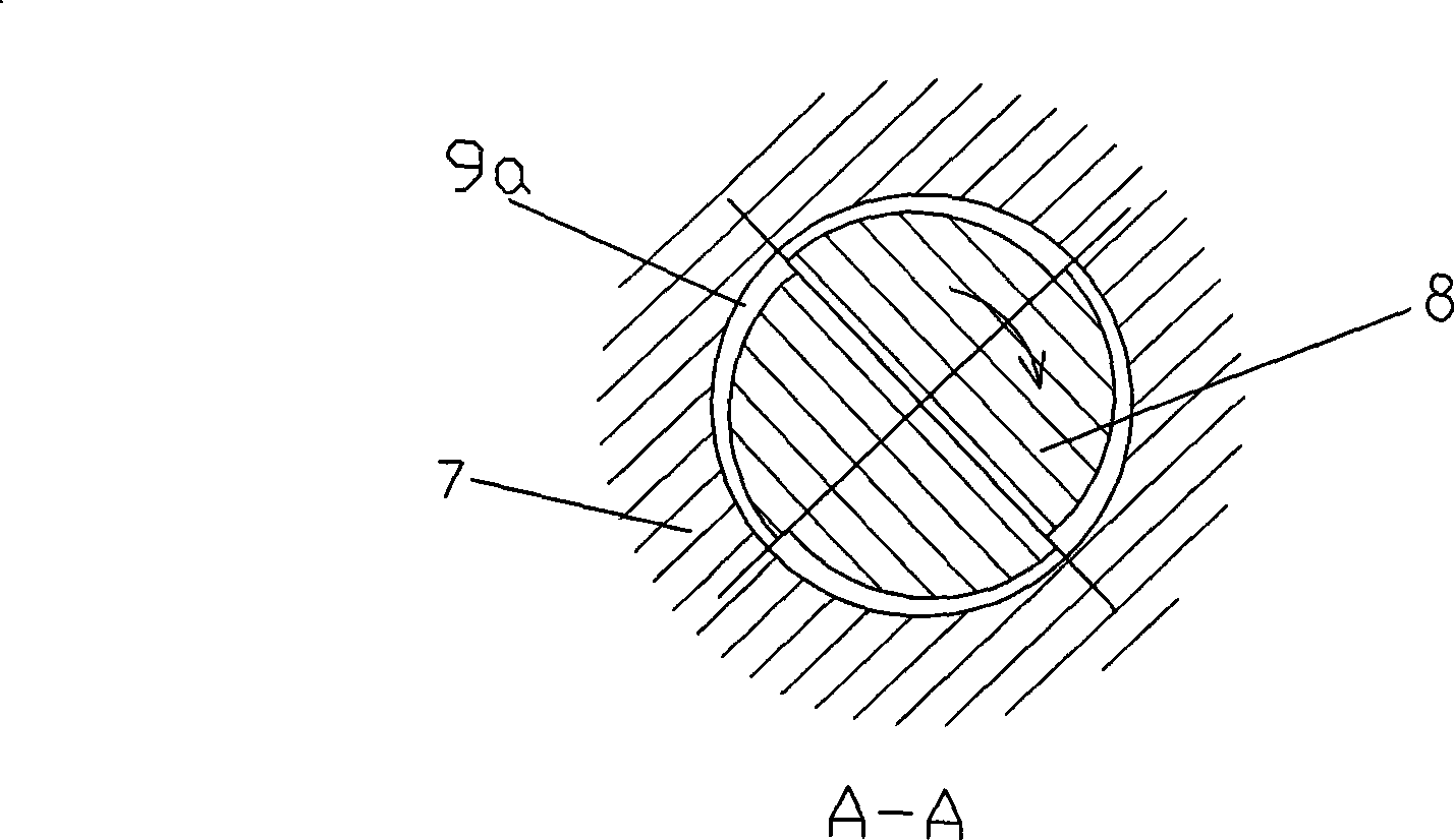
[0015] In this example, if figure 1 As shown, a section of pressure-bearing groove 9 is set at the front end of shaft 8, such as figure 2 As shown, the cross-section of the pressure-bearing groove 9 is a wedge-shaped groove 9a arranged in segments along the circumference. The wedge-shaped groove 9a takes the deep groove end as the groove head, takes the shallow groove end as the groove tail, and transitions with a circular arc in between. The head of the intermediate groove is connected with the tail of the groove, and the liquid supply channel 1 communicates with the wedg...


PUM


Abstract

The invention relates to a hydrodynamic pressure auxiliary support tool bar and a support method thereof. The tool bar is provided with a bar head, a bar neck and a bar body, wherein, a central axial hole of the bar body is arranged as a cutting liquid feeding channel which is communicated with a cutting liquid flow channel of the bar neck. The invention is characterized in that a section of bearing groove is arranged at the front end of the bar body, the cross section of the bearing groove is a wedge-shaped groove which is radially arranged along the circumference, and the wedge-shaped groove takes the deep groove end as a groove head and the shallow groove end as a groove tail and an arc transition is adopted between the groove head and the groove tail; the groove heads and the groove tails are connected among all sections of wedge-shaped groove; the liquid feeding channel is communicated with the wedge-shaped groove through the cutting liquid flow channel of the bar neck; and the cutting liquid along the circumference in the wedge-shaped groove corresponding to the rotation of a circular tool bar flows from the groove heads to the groove tails. The invention utilizes the specific shape of the surface of the tool bar to ensure that the tool bar, processed holes of a workpiece and the cutting liquid automatically form a hydrodynamic pressure support system provided with a wedge-shaped oil film during the processing courses of the tool; and the tool bar is supported in the processed hole by the oil film, thereby the rigidity of the tool bar can be strengthened.

Description

technical field [0001] The invention relates to the technical field of precision machining, more specifically to a tool bar and a tool bar supporting method, a boring tool or a reamer tool bar and a tool bar supporting method used in precision boring pins or reaming. Background technique [0002] When using a boring tool or reamer for precision boring or reaming holes, the bending and vibration of the tool bar have a great impact on the processing quality, especially for the precision machining of long and thin holes. In order to increase the rigidity of the boring bar or reamer bar when precision boring or reaming holes, to reduce the bending and vibration of the boring bar or reamer bar, and to improve the machining accuracy, it is possible to set up auxiliary supports on the bar , For example, set "rigid" auxiliary supports such as support bars or support blocks to support the tool holder. However, for the tool bar structure with auxiliary support of support bars or supp...

Claims


Application Information

Patent Timeline
Patent Type & Authority Applications(China)
IPC IPC(8): B23B27/00B23B29/02B23D77/00
Inventor 黄斌
Owner HEFEI UNIV OF TECH
Why Eureka
Try Eureka