Laser processing device using laser beam induced into jet column

A laser processing and laser beam technology, applied in laser welding equipment, metal processing equipment, manufacturing tools, etc., can solve problems such as the reduction of laser beam propagation efficiency, and achieve the effect of preventing degradation, ensuring optical performance, and avoiding thermal deformation.

Active Publication Date: 2009-04-01
SUGINO MACHINE
View PDF5 Cites 49 Cited by
  • Summary
  • Abstract
  • Description
  • Claims
  • Application Information

AI Technical Summary

Problems solved by technology

Therefore, the propagation efficiency of the laser beam is reduced due to the disturbance of the water jet

Method used


Image

  • Laser processing device using laser beam induced into jet column
  • Laser processing device using laser beam induced into jet column
  • Laser processing device using laser beam induced into jet column

Examples


Embodiment Construction

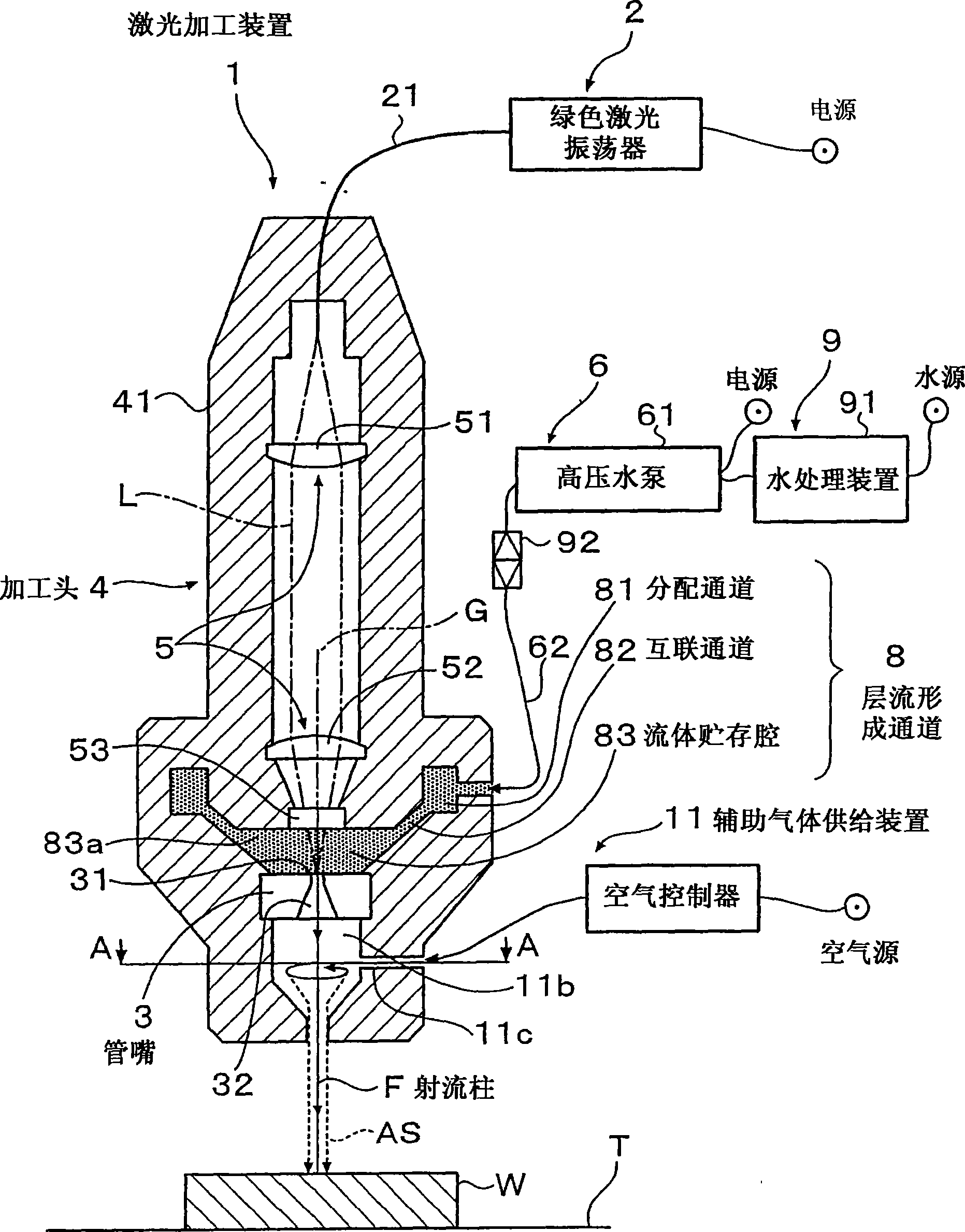
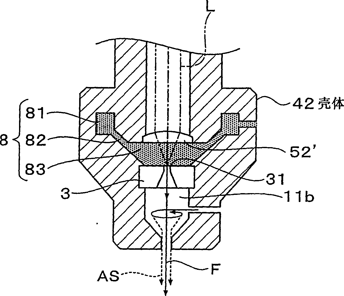
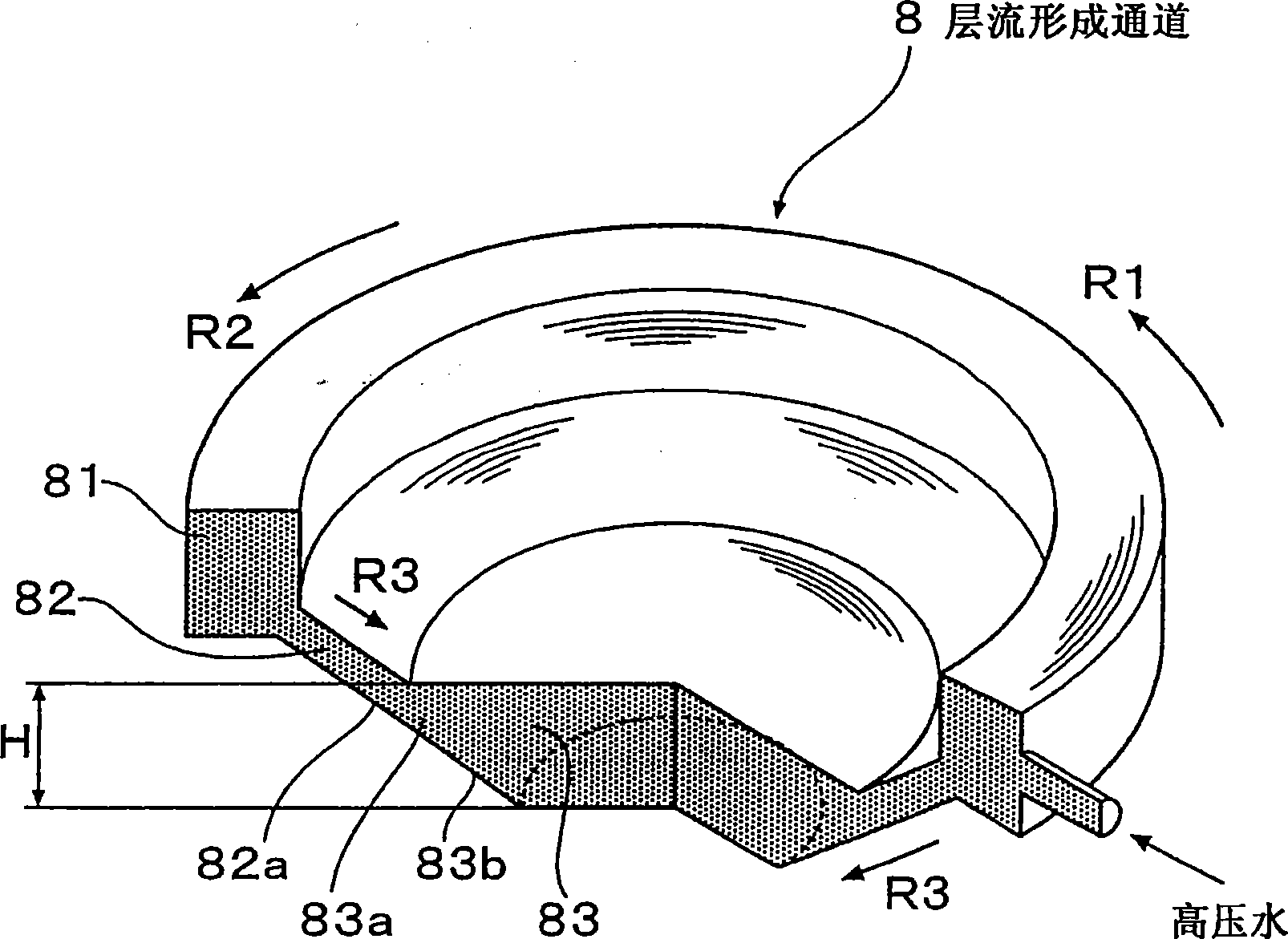
[0066] A laser processing apparatus according to an embodiment of the present invention will be described in detail below with reference to the accompanying drawings.

[0067] In the attached drawings mentioned here, figure 1 The shown side sectional view shows the overall structure of the laser processing device according to the embodiment of the present invention. figure 2 is a partial enlarged view for explaining another example of the optical device used in the embodiment of the present invention, which shows the case where the laser beam guide window is not provided. image 3 The perspective view shown shows the shape of the laminar flow forming channel according to the embodiment of the present invention. Figure 4 is along figure 1 A cross-sectional view of line A-A in , which shows the structure of the spiral guide channel in the auxiliary gas supply device according to the embodiment of the present invention. Figure 5 The shown side sectional view shows the stru...


PUM

PropertyMeasurementUnit
wavelengthaaaaaaaaaa

Abstract

A laser machining apparatus comprises a nozzle for ejecting a jet liquid to a workpiece and a liquid supply unit for supplying the jet liquid to the nozzle, while a laser beam is introduced into a jet liquid column ejected from the nozzle. The laser machining apparatus further comprises a laminar flow forming channel for supplying the jet liquid to the nozzle in a laminar state. The laminar flow forming channel includes a distribution channel formed by a cavity for annually distributing the jet liquid, which is supplied from the liquid supply unit, around an axis of the nozzle, an interconnecting channel disposed to be communicated with the distribution channel at the downstream side thereof in an axial direction of the nozzle and formed by an annular cavity around the axis of the nozzle to provide a narrower flow passage than the distribution channel, and a liquid reservoir chamber adjacently disposed upstream of the nozzle in the axial direction thereof and storing the jet liquid tobe supplied to the nozzle. The liquid reservoir chamber has an outer peripheral edge being communicated with the interconnecting channel over an entire circumference of the annular shape thereof.

Description

technical field [0001] The present invention relates to a laser processing (processing) device using a laser beam introduced into a jet liquid column. More particularly, the present invention relates to a laser processing device using a laser beam introduced into a jet column, which can improve the propagation efficiency of the laser beam and can ensure stable processing quality. Background technique [0002] Hitherto, there has been known an apparatus for irradiating a laser beam into a jet column of an electrolytic solution for plating or etching, which performs plating or etching on a substrate using a technique of introducing a laser beam through the jet column. There is also known a treatment device that cuts a portion to be treated using a water column and a laser beam, irradiates the laser beam into the water column, and propagates the laser beam in the water column using total reflection. [0003] This technique of introducing a laser beam into a fluid column by tot...

Claims


Application Information

Patent Timeline
Patent Type & Authority Applications(China)
IPC IPC(8): B23K26/12B23K26/06B23K26/14
CPCB23K26/06B23K26/08B23K26/1224B23K26/146
Inventor 村椿良司永田幸明杉森正
Owner SUGINO MACHINE
Why Eureka
Try Eureka