Milling machine outrigger elevator apparatus and pavement milling machine using the same

A lifting device and milling machine technology, which is applied in the field of road milling machines, can solve the problems that the milling depth cannot be adjusted quickly and accurately, the lifting speed control does not adopt stepless adjustment, and the construction quality of the milling surface does not meet the requirements, etc. , to eliminate the danger of tipping, improve the construction quality, and eliminate the effects of interference

Active Publication Date: 2009-04-01
益阳市科技成果转化服务中心 +1
View PDF0 Cites 17 Cited by
  • Summary
  • Abstract
  • Description
  • Claims
  • Application Information

AI Technical Summary

Problems solved by technology

[0004] It is difficult to achieve the same lifting height of each leg if it is lifted separately, which is not conducive to adjusting the lifting of the legs at the beginning of milling or in the process of milling, so that the milling depth cannot be adjusted quickly and accurately, and the construction quality of the milling surface may not meet the requirements.
[0005] Synchronous lifting, because the oil cylinders of the outriggers (especially the two front outriggers) of the milling machine bear different weights on the feeding mechanism, the structure for realizing synchronous lifting is relatively complicated, and mutual interference between the cylinders of the outriggers is also easy to occur; at the same time , because stepless adjustment measures are not adopted for the control of the lifting speed of the outriggers, the outriggers bear variable loads during the swinging operation of the conveying mechanism, and their synchronization accuracy is poor
In addition, once there is a problem with the pipeline, the outrigger cannot be effectively locked, which may easily cause the milling machine to tip over and cause an accident

Method used


Image

  • Milling machine outrigger elevator apparatus and pavement milling machine using the same
  • Milling machine outrigger elevator apparatus and pavement milling machine using the same

Examples


Embodiment Construction
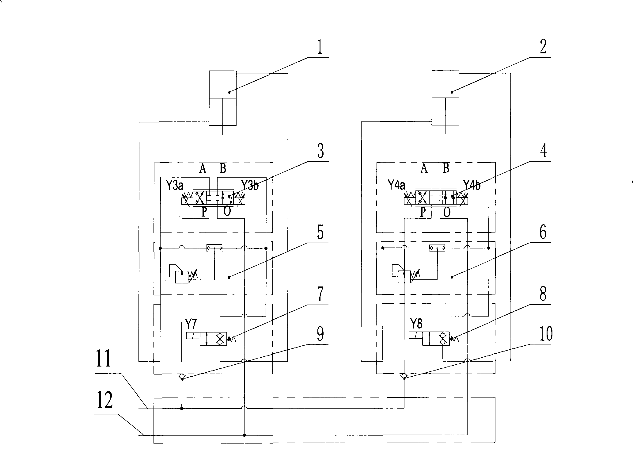
[0023] The basic idea of ​​the present invention is to set left and right proportional reversing valves in the oil circuit where the left and right outrigger oil cylinders are located, so as to control the telescopic action speed of the left and right outrigger oil cylinders and realize the stepless lifting and lowering speed of the outriggers. Adjustment to improve the synchronous lifting accuracy of the outriggers; left and right pressure compensators to stabilize the pressure of the left and right outrigger cylinders to ensure that the actions of the two do not interfere.

[0024] The following will be described in detail in conjunction with the embodiments and accompanying drawings.

[0025] Please refer to figure 1 , which is a hydraulic schematic diagram of a preferred embodiment of the milling machine leg lifting device of the present invention. figure 1 The leg lifting device of the milling machine shown includes: left outrigger cylinder 1, right outrigger cylinder 2,...


PUM


Abstract

The invention discloses a support lifting device of a milling machine, which comprises a left support oil cylinder and a right support oil cylinder. The support lifting device is used for adjusting the heights of a left leg and a right leg by flexible actions of the left support oil cylinder and the right support oil cylinder. The support lifting device also comprises a left proportional and directional valve and a right proportional and directional valve which are communicated with the left support oil cylinder and the right support oil cylinder respectively through oil circuits and used for controlling the speed of the flexible actions of the left support oil cylinder and the right support oil cylinder; and a left pressure compensator and a right pressure compensator, which are also included by the device, and are respectively installed on the oil circuits between the left proportional and directional valve and the left support oil cylinder and between the right proportional and directional valve and the right support oil cylinder and used for stabilizing the pressures of the left support oil cylinder and the right support oil cylinder. The proportional valves can not only reverse the directions, but also can adjust the flow rate, thereby being capable of adjusting the direction and the speed of the flexible actions of the support oil cylinders to realize the infinitely variable control of the lifting speed of the legs with comparatively high synchronous precision; and the pressure compensators can stabilize the pressure of the oil cylinder and eliminate the load difference between the support oil cylinders so as to ensure no interaction in the actions of the two oil cylinders. The invention also discloses a road milling machine using the support lifting device.

Description

technical field [0001] The invention relates to equipment or devices for processing completed road surfaces, in particular to a milling machine outrigger lifting device and a road surface milling machine using the outrigger lifting device. Background technique [0002] Road milling machine (hereinafter referred to as milling machine) is an efficient road maintenance machinery and equipment, which is mainly used for the excavation and renovation of asphalt concrete surfaces such as highways, airports, freight yards, and parking lots. This kind of milling machine can efficiently remove the bumps and waves of the road surface, and can also dig pits or grooves on the road surface, and can also be used for roughening of the cement concrete road surface or milling and flattening of the surface layer. [0003] In order to ensure the construction quality of the milling surface, it is necessary to adjust the height of the legs of the milling machine according to the construction site...

Claims


Application Information

Patent Timeline
Patent Type & Authority Applications(China)
IPC IPC(8): E01C23/088
Inventor 段方亮李建科汪建利
Owner 益阳市科技成果转化服务中心
Why Eureka
Try Eureka