Novel mass flow blade mechanism

A large flow and vane technology, applied in the field of new structure, can solve the problems of increased volume, increased cost, high pressure, etc., and achieve the effects of small frictional resistance, easy low-speed work, and low cost

Inactive Publication Date: 2009-04-01
陈军
View PDF0 Cites 6 Cited by
  • Summary
  • Abstract
  • Description
  • Claims
  • Application Information

AI Technical Summary

Problems solved by technology

[0002] At present, many existing pump products have the problems of high pressure but small flow, large flow but low pressure. To solve these problems, it is necessary to increase the volume and increase the cost. Find a reasonable solution between the two. Become the main problem that the present invention solves

Method used


Image

  • Novel mass flow blade mechanism
  • Novel mass flow blade mechanism
  • Novel mass flow blade mechanism

Examples


Embodiment Construction

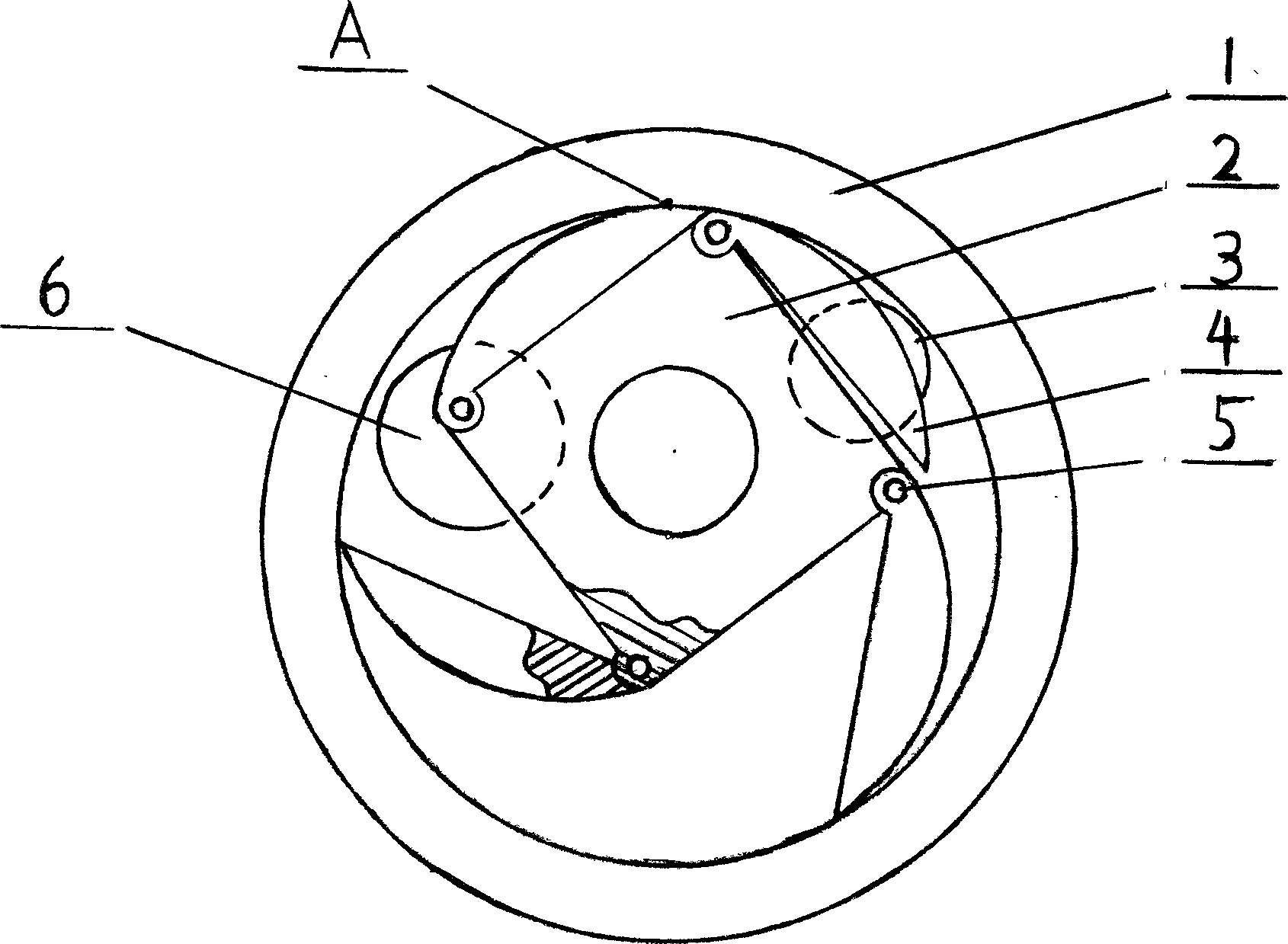
[0013] Such as figure 1 As shown, the novel high-flow vane mechanism provided by the present invention has a stator 1, a rotor 2, an oil inlet 3, a vane 4, a hinged connecting pin 5, and an oil outlet 6. The four corners of the square rotor 2 are respectively hinged with small semicircular blades 4-1, 4-2, 4-3, and 4-4 through pins 5, which are combined into a circle and installed in the stator 1. . The outer circle formed by the rotor 2 and the vanes 4 is in contact with the inner wall of the stator 1 at point A on the upper end, and the vanes 4 opened with the hinged connecting pin 5 at the corner of the rotor 2 as the center of the circle are in contact with the inner wall of the stator 1 during the compression process to form a closed space .

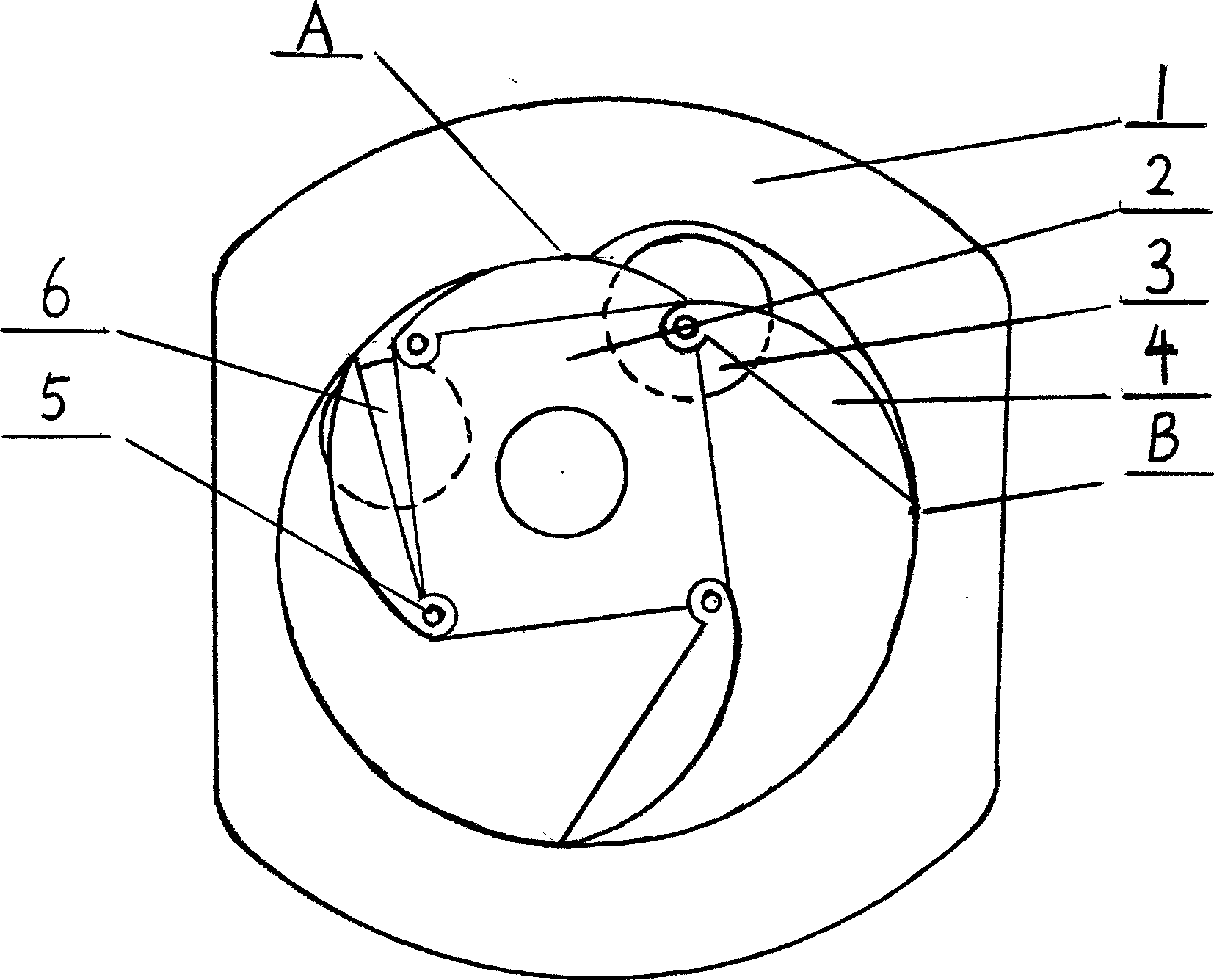
[0014] Such as figure 2 As shown, the arc radius of the point B on the inner wall of the stator 1 in the oil inlet 3 is increased, and the volume of the oil inlet 3 and the capacity between the blades 4 are increased. And lengt...


PUM


Abstract

The invention relates to a novel large-flow vane pump or motor, which is provided with a stator 1, a rotor 2, an oil inlet 3, a vane 4, an articulated connecting pin 5 and an oil outlet 6. The five angles of the pentagonal rotor are connected with a vane 4-1, a vane 4-2, a vane 4-3 and a vane 4 respectively which are in a small semicircle-shape by the articulated connecting pin 5, form a circle jointly and are arranged in the stator 1. An excircle formed by the rotor 2 and the vane 4 is in contact with a point A at the upper end of the inner wall of the stator 1 and the excircle and the open vane 4 opened by a centrifugal force are in contact with the inner wall of the stator 1 during the compression process to form a closed space. Liquid is adsorbed into the stator 1 by the oil inlet 3; the rotor 2 rotates at a high speed; each vane of the vane 4 is fast opened under the effect of the centrifugal force, drives the liquid in the stator 1 to be discharged from the oil outlet 6; and as one end of the vane 4 is connected with the corner of the excircle of the rotor 4, the distance between the rotor 2 and the inner wall of the stator 1 after the vane 4 is opened is increased, so flow is increased at the same rotating speed.

Description

Technical field: [0001] The invention belongs to a novel structure of a pump or a motor, which is suitable for pneumatic and hydraulic pumps or motors. Background technique [0002] At present, many existing pump products have the problems of high pressure but low flow, large flow but low pressure. To solve these problems, it is necessary to increase the volume and increase the cost. Find a reasonable solution between the two. Become the main problem that the present invention solves. Contents of the invention [0003] The novel pump body provided by the invention consists of a rotor, a stator and blades. In order to obtain the maximum flow effect, this design changes the shape and structure of the stator, rotor and blades. [0004] The present invention has three or more blade designs. Taking a four-blade hydraulic pump as an example, the original circular rotor is changed into a circular shape composed of the rotor and blades, and the blades are changed from straight b...

Claims


Application Information

Patent Timeline
Patent Type & Authority Applications(China)
IPC IPC(8): F01C1/44F04C2/44F04C18/44
Inventor 陈军
Owner 陈军
Why Eureka
Try Eureka