

Synthesis measurement method and device for manufacturing engineering machinery hydraulic components
A technology of comprehensive measurement and construction machinery, applied in the field of measurement, can solve the problems of inconvenient on-site spot checks for processors, increase the workload of measurement units, and prolong the product trial production cycle, so as to reduce the development cost and cycle, improve the development and production efficiency, The effect of shortening the trial production cycle
- Summary
- Abstract
- Description
- Claims
- Application Information
AI Technical Summary
Problems solved by technology
Method used
Image

Examples
Embodiment Construction
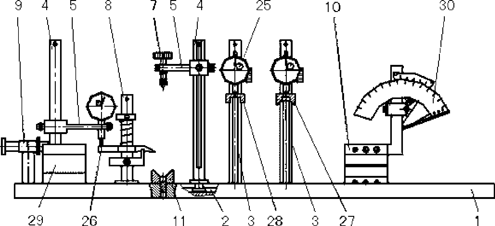
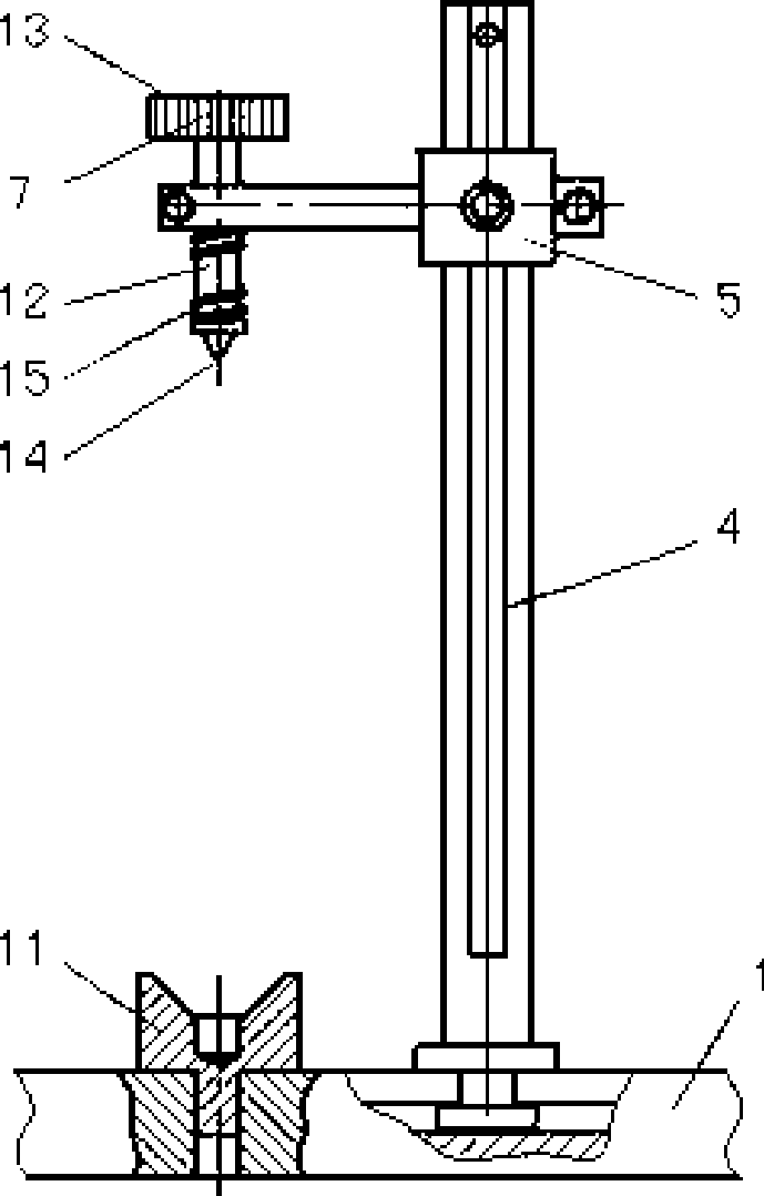
[0029] Example. Comprehensive measuring method and measuring device for manufacturing hydraulic parts of construction machinery. Such as figure 1 , figure 2 As shown, the method completes the measurement of various engineering machinery hydraulic parts by constructing a comprehensive measuring device and using conventional measuring tools; The column is divided into a fixed column 3 and a movable column 4, the fixed column 3 is an interference fit with the platform 1, and its position is fixed and cannot be moved. The movable column 4 can move on the platform 1 by the guide groove 2, and is fixed with the platform 1 by pressing the nut; the comprehensive measuring device is also equipped with a measuring rod positioning assembly 8 and a vertical positioning assembly 7 for positioning the measured parts And horizontal positioning assembly 9.
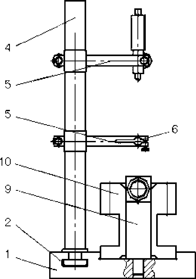
[0030] The above mentioned vertically positioned components such as image 3 As shown, it includes a movable column 4 with an orie...
PUM
 Abstract
Description
Claims
Application Information