
Clamp optimization method for aero-engine blade clamping heat treatment

An aero-engine and optimization method technology, applied in heat treatment furnaces, heat treatment equipment, design optimization/simulation, etc., can solve the problem that the blade body cannot be vertically hung on it, so as to improve the development and production efficiency, reduce heat treatment deformation, Improve the effect of matching

Active Publication Date: 2021-02-23
CHINA HANGFA GUIZHOU LIYANG AVIATION POWER CO LTD
View PDF4 Cites 1 Cited by
  • Summary
  • Abstract
  • Description
  • Claims
  • Application Information

AI Technical Summary

Problems solved by technology

In addition, the inner surface of the mortise of most of the blades in production is a non-simple plane such as an arc surface or a conical surface, and the blade structure is irregular and its center of gravity is not at the geometric center. At present, there is no effective way to judge the actual gravity of the blade before manufacturing the heat treatment fixture. Whether it is vertically hung on the fixture or not, this will cause the heat treatment fixture actually designed and manufactured not to make the blade body close to the ideal vertical suspension on it, and there will often be a deflection difference of several degrees or even more than ten degrees

Method used


Image

  • Clamp optimization method for aero-engine blade clamping heat treatment
  • Clamp optimization method for aero-engine blade clamping heat treatment
  • Clamp optimization method for aero-engine blade clamping heat treatment

Examples


specific Embodiment

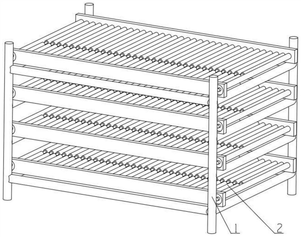
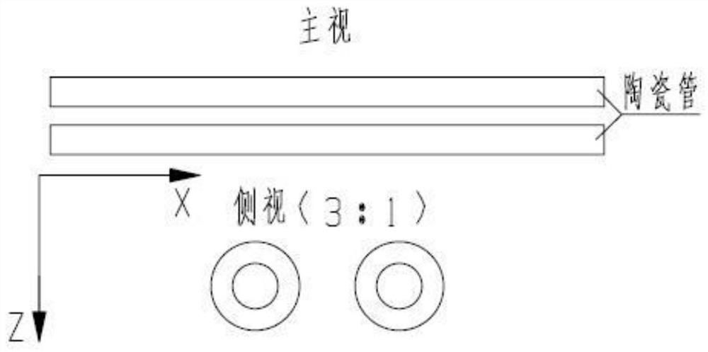
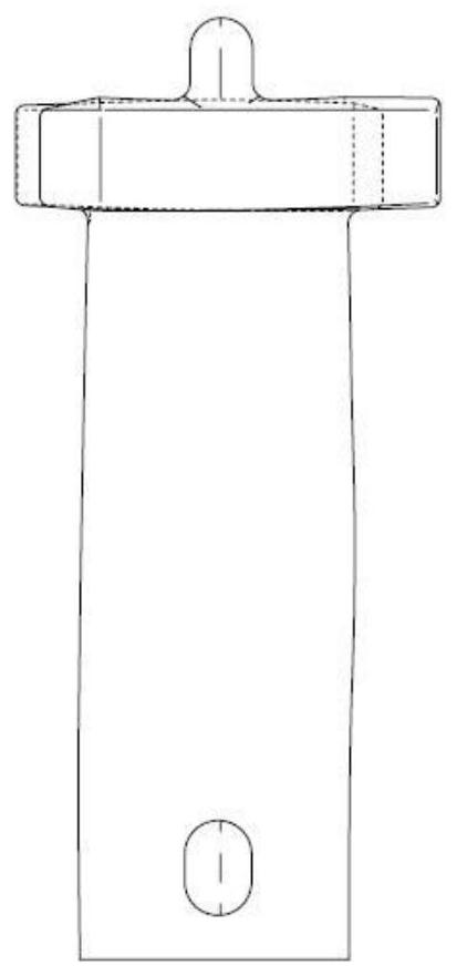
[0032] figure 1 The schematic diagram shown is the optimized fixture object in the specific embodiment of the method of the present invention—the combined material rack, which is composed of the main body of the material rack 1 and the material tray 2; image 3 The schematic diagram of the solid shape of the blade shown is the precision forged blade suspended on the fixture in the specific embodiment of the method of the present invention. According to the structural characteristics and solid shape of the precision forged blade, it is made by connecting the points of the blade body section X=0 Its leaf spread forms lines such as Figure 5 As shown, the analysis of its back-toward blade span line and basin-toward blade span line finds that it is basically parallel to the Z direction, and the axial direction of the blade tip positioning journal of the precision forging blade design is the Z direction, so in this specific embodiment, the blade After being hung on the fixture and...


PUM


Abstract

The invention discloses a clamp optimization method for aero-engine blade clamping heat treatment. The clamp optimization method comprises the following steps that S01, establishing a clamp basic model and a blade workpiece model; s02, simulating the state that the aero-engine blade is suspended on the clamp under the action of gravity; s03, carrying out optimal data analysis of the heat treatmentclamp; and S04, optimizing the heat treatment clamp according to a data analysis result. The heat treatment clamp is optimized according to the analysis data of the suspension state of the blade on the heat treatment clamp, so that the blade body of the blade can be approximately ideally and vertically suspended on the actually designed and manufactured heat treatment clamp in actual production,and the heat treatment deformation of the blade is reduced; the consistency between blade machining and manufacturing and a design drawing is improved, and blade machining and manufacturing cost is reduced. Meanwhile, the clamp is optimized through a method of simulating a real object and a scene instead of a real object test, so that the material cost is saved, the manufacturing period is shortened, and the blade development and production efficiency is improved.

Description

technical field [0001] The invention relates to a fixture optimization method for clamping and heat treatment of aeroengine blades. Background technique [0002] At present, in the actual application process of blade heat treatment, in order to reduce the heat treatment deformation caused by its own weight and mutual extrusion, the heat treatment is often carried out by hanging. Wuxi Turbine Blade Co., Ltd. patent CN204455214U "A Charging Structure for Reducing Heat Treatment Deformation of Steam Turbine Blade Forgings" describes a charging structure, which can use the self-weight of the blade to freely hang the blade on it for heat treatment to reduce heat treatment. Deformation; Xi'an Aviation Power Co., Ltd. patent CN204097530U "A Combined Material Rack for Precision Forging Blade Vacuum Heat Treatment" specification also discloses a combined material rack, which can make the blade body with a slope in the tenon length direction Hanging vertically on it to reduce heat tr...

Claims


Application Information

Patent Timeline
Patent Type & Authority Applications(China)
IPC IPC(8): G06F30/20G06F30/17C21D9/00G06F119/14
CPCG06F30/20G06F30/17C21D9/0068G06F2119/14
Inventor 陆彦良陈玉珍夏玥胡吉云黄联杰陈琳
Owner CHINA HANGFA GUIZHOU LIYANG AVIATION POWER CO LTD
Learn More