Carriage lateral movement-limiting system

A bogie and traverse technology, which is applied to railway car body parts, roads, and railway derailment prevention, etc., can solve problems such as damage to the running track, bad riding feeling, increase in the weight of the bogie, etc., and achieve the effect of easy wear and tear.

Inactive Publication Date: 2009-04-01
NIPPON SHARYO
View PDF1 Cites 16 Cited by
  • Summary
  • Abstract
  • Description
  • Claims
  • Application Information

AI Technical Summary

Problems solved by technology

[0004] However, the above-mentioned overturning prevention system requires greater strength in the axle box where the limiter device is installed, so the weight of the bogie as a whole increases, and in addition due to the increase in the weight of the unsprung Increase, may have adverse effects on the riding experience, and also have the effect of causing damage to the running track when passing through a switch or a switch

Method used


Image

  • Carriage lateral movement-limiting system
  • Carriage lateral movement-limiting system
  • Carriage lateral movement-limiting system

Examples


Embodiment Construction

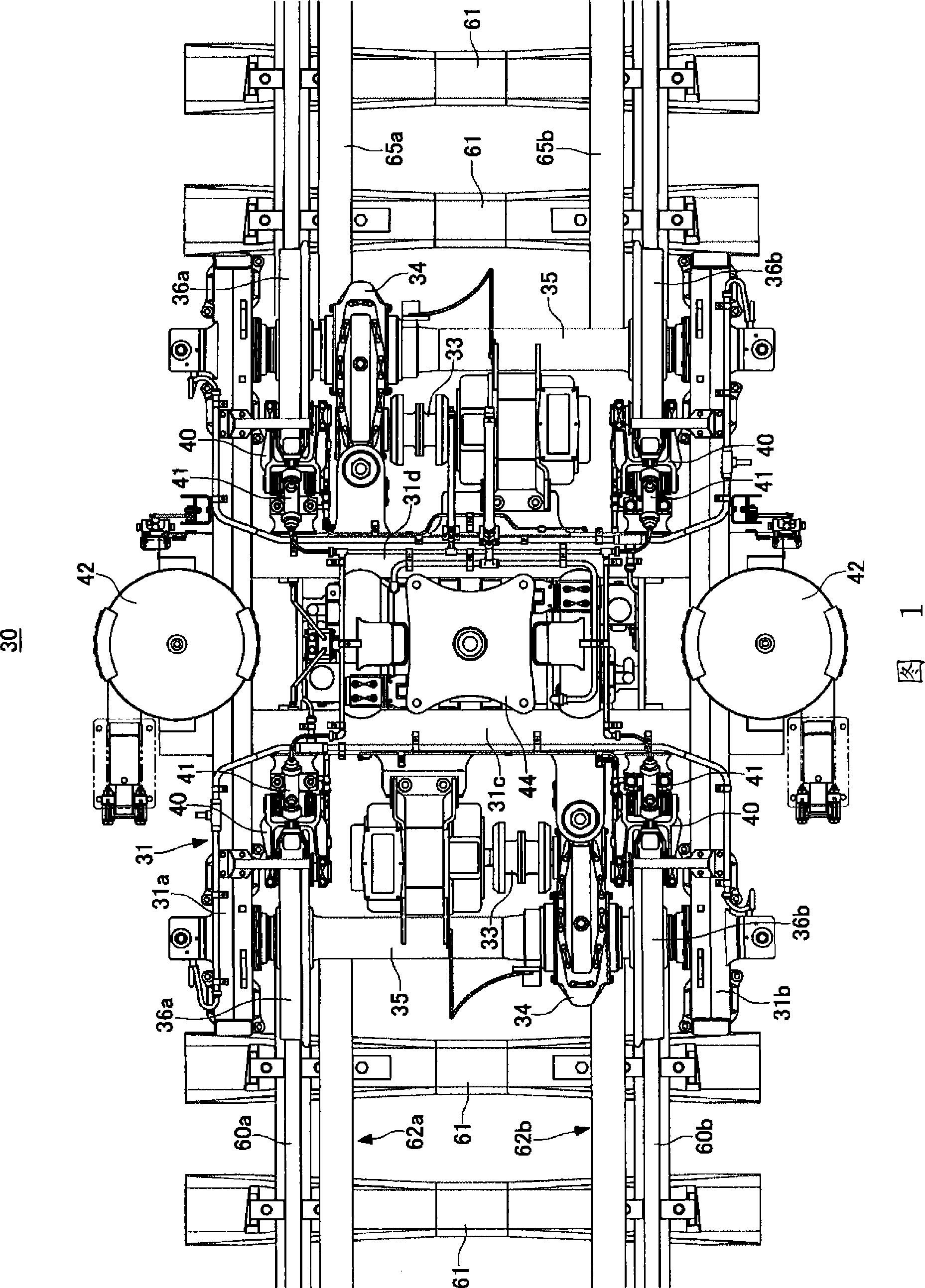
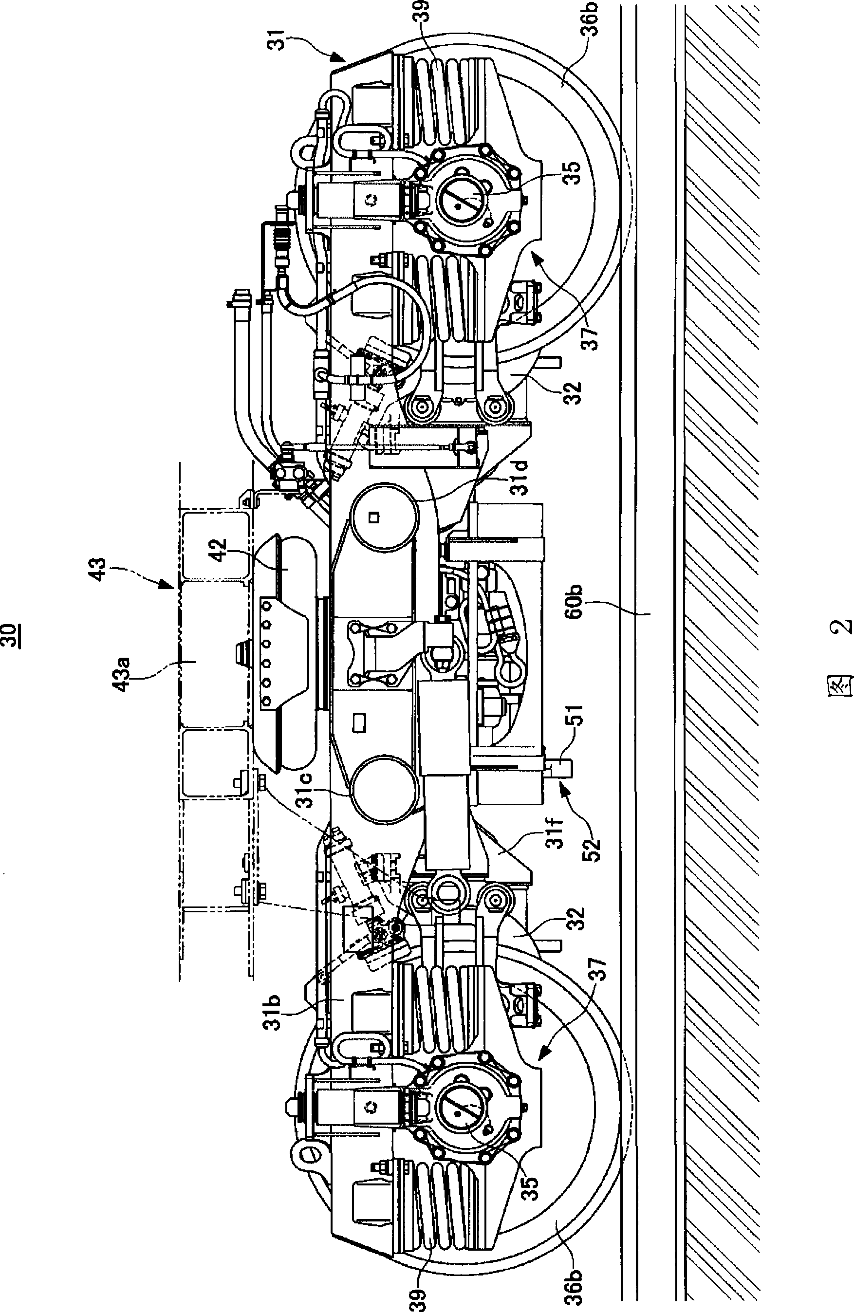
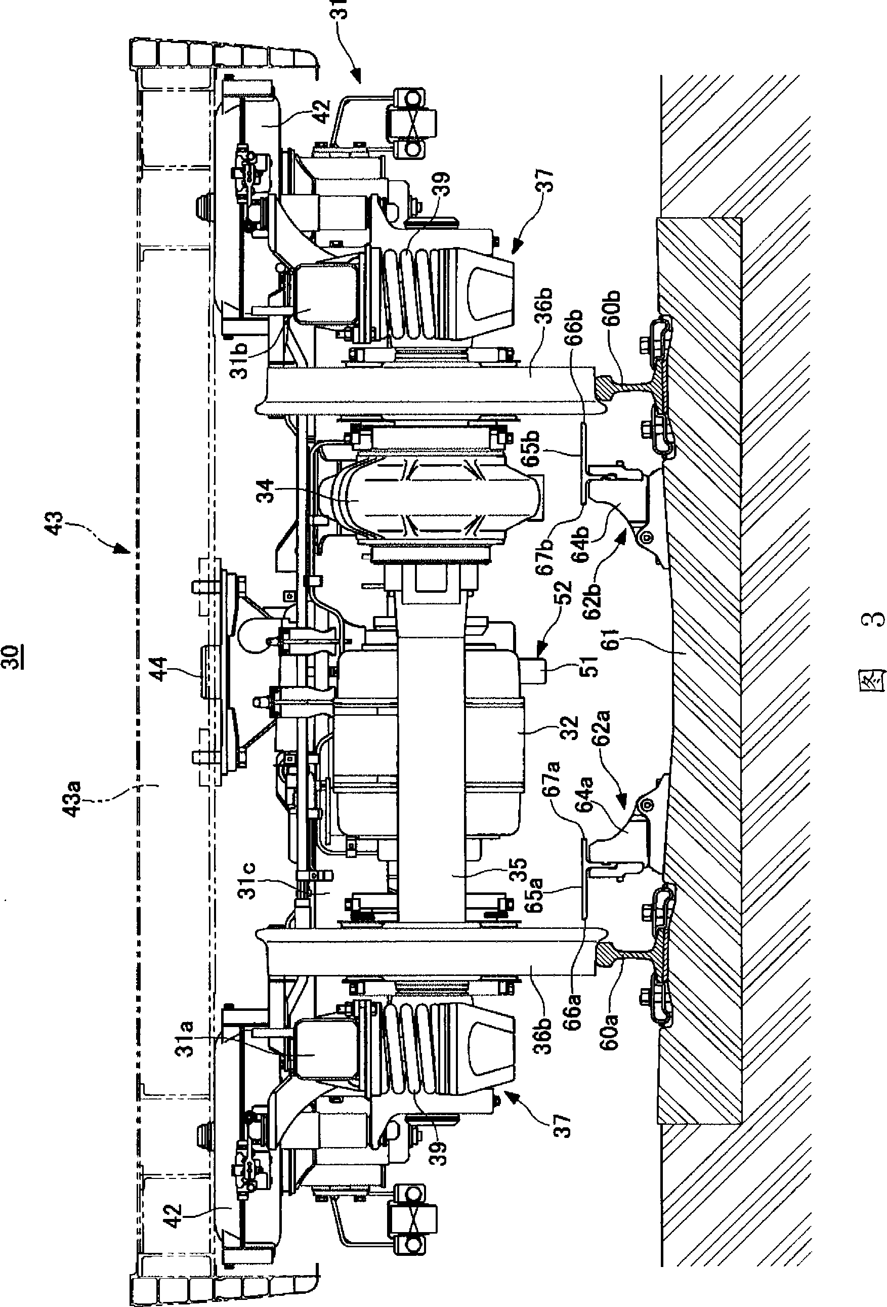
[0034] 1-3 show an embodiment of the electric bogie used in the bogie traverse limiting system of the present invention, FIG. 1 is a plan view, FIG. 2 is a side view, and FIG. 3 is a front view. The bogie 30 illustrated in this embodiment is a bolsterless bogie for an electric vehicle. In this bogie 30, two side beams 31a, 31b parallel to the left and right rails 60a, 60b and two crossbeams 31c, 31d parallel to the crossties 61 constitute a substantially H-shaped bogie frame 31 in plan view. Main motors 32 are respectively fixed to the two beams 31c and 31d. The rotational force of the main motor 32 is transmitted to the axle 35 and the left and right wheels 36a, 36b through the flexible coupling 33 and the gear unit 34 . The two ends of the side beams 31 a and 31 b are provided with axle boxes 37 for supporting the two ends of the axle 35 . An axle spring 39 is provided between each axle box 37 and the side beams 31a, 31b. Disc brake devices 40 are provided on the beams 31...


PUM


Abstract

A carriage lateral movement-limiting system capable of effectively restricting the lateral movement of a derailed carriage. The system comprises derailment prevention guards (62a, 62b) laid along the inside of paired left and right rails (60a, 60b), and a lateral movement-limiting device (52) installed on the lower part of the carriage (30). The device (52) has a stopper (51) projecting downward at a position between the wheels (36a, 36b) of the carriage and brought into slidingly contact with the inner surfaces of the derailment prevention guards (62a, 62b) when the carriage is derailed.

Description

technical field [0001] The present invention relates to a bogie lateral movement limiting system, in particular, to a bogie lateral movement limiting system capable of preventing secondary disasters by limiting the lateral movement of the bogie when a railway vehicle derails due to an earthquake or strong wind . Background technique [0002] As a device used to prevent the vehicle from tipping over by guiding the vehicle to run on a track bed with sleepers, a roadbed, etc. when the railway vehicle is derailed due to natural disasters such as earthquakes and strong winds, a stopper device is proposed that is arranged at the lower part of the axle box. A fall-over prevention system in which a stopper device contacts a rail when derailed and restrains the vehicle from being displaced in the width direction (for example, refer to Patent Document 1.). [0003] Patent Document 1: Japanese Patent No. 3393032 [0004] However, the above-mentioned fall prevention system requires a ...

Claims


Application Information

Patent Timeline
Patent Type & Authority Applications(China)
IPC IPC(8): B61F9/00E01B5/18
CPCE01B5/18B61F9/00
Inventor 坂上启南善德国井利树高田伸久
Owner NIPPON SHARYO
Why Eureka
Try Eureka