Fluid dynamic pressure bearing device and method of producing the same

A technology of fluid dynamic pressure bearings and bearing devices, which is applied in the direction of sliding contact bearings, rotary motion bearings, bearings, etc., can solve the problems of assembly accuracy reduction and poor bearing performance, achieve high bending rigidity, and avoid assembly accuracy and bearing performance reduction effect

Inactive Publication Date: 2009-04-01
NTN CORP
View PDF2 Cites 7 Cited by
  • Summary
  • Abstract
  • Description
  • Claims
  • Application Information

AI Technical Summary

Problems solved by technology

In this intermediate bending state, the subsequent assembly accuracy will decrease, and it will also have a bad influence on the bearing performance

Method used


Image

  • Fluid dynamic pressure bearing device and method of producing the same
  • Fluid dynamic pressure bearing device and method of producing the same
  • Fluid dynamic pressure bearing device and method of producing the same

Examples


Embodiment Construction

[0059] Embodiments of the present invention will be described below with reference to the drawings.

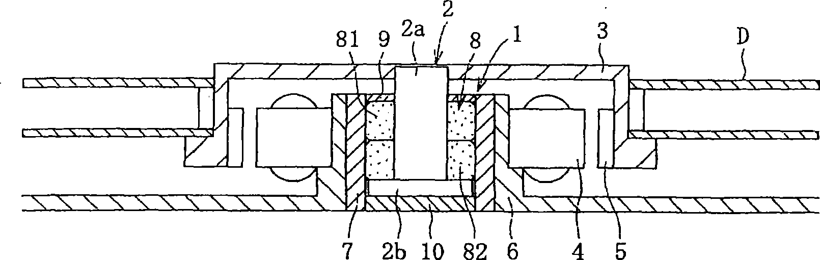
[0060] figure 1 A configuration example of a spindle motor for information equipment incorporating the fluid dynamic pressure bearing device 1 as an example of the fluid dynamic pressure bearing device of the present invention is schematically shown. This spindle motor is used in a disk drive device such as an HDD, and includes a fluid dynamic pressure bearing device 1 that supports a shaft member 2 in a non-contact manner so as to be rotatable, a rotor (hub) 3 mounted on the shaft member 2, and, for example, a radius The stator coil 4 and the rotor magnet 5 are opposed to each other at intervals in the direction. The stator coil 4 is installed on the outer periphery of the bracket 6 , and the rotor magnet 5 is installed on the inner periphery of the hub 3 . The casing 7 of the fluid dynamic pressure bearing device 1 is mounted on the inner periphery of the bracket 6 . The...


PUM


Abstract

A fluid dynamic pressure bearing device that achieves high rigidity against moment without a reduction in assembly accuracy and bearing performance. In the bearing device, bearing sleeves are arranged in the axial direction and coaxiality of radial bearing surfaces formed on the inner peripheral surfaces of the bearing sleeves is set to 3 [mu]m or less. This secures width accuracy between the radial bearing gaps to prevent a reduction in bearing performance and a failure such as wear etc. caused by contact between a shaft member and the bearing sleeves. Further, a first radial bearing surface and a second radial bearing surface are provided on at least one sleeve, and this allows a sleeve assembly constructed from bearing sleeves to be supported at least three positions in the axial direction in a process of assembling the sleeve assembly. As a result, assembly work can be carried out with two bearing sleeves prevented from being bent in the middle and highly accurate coaxiality between both bearing sleeves secured.

Description

technical field [0001] The invention relates to a fluid dynamic pressure bearing device. Background technique [0002] A hydrodynamic bearing device is a device that generates pressure under the dynamic pressure of a fluid (lubricating fluid) generated in a bearing gap with the relative rotation of a bearing sleeve and a shaft member inserted into the inner circumference of the bearing sleeve, relying on the A bearing device for pressure non-contact supporting a shaft member. Fluid dynamic pressure bearing devices are broadly classified into those having a dynamic pressure generating portion that actively generates dynamic pressure in the lubricating fluid in the bearing gap, and those having no such dynamic pressure generating portion and having the inner peripheral surface of the bearing sleeve and the outer peripheral surface of the shaft member uniform. It is a so-called perfect circle bearing with a cylindrical surface. [0003] This fluid dynamic pressure bearing dev...

Claims


Application Information

Patent Timeline
Patent Type & Authority Applications(China)
IPC IPC(8): F16C17/02F16C43/02F16C17/10
CPCF16C17/02F16C33/107F16C17/107F16C17/04Y10T29/49639
Inventor 山下信好户田正明尾藤仁彦堀政治
Owner NTN CORP
Why Eureka
Try Eureka