Lathe

A technology for lathes and fixtures, applied in the field of lathes, can solve the problems of complex lathe structures and increase the manufacturing cost of lathes, and achieve the effects of saving power sources, rational design, and reducing manufacturing costs.

Active Publication Date: 2009-04-08
ZHEJIANG SHUANGZHENG MACHINE TOOL CO LTD
View PDF5 Cites 13 Cited by
  • Summary
  • Abstract
  • Description
  • Claims
  • Application Information

AI Technical Summary

Problems solved by technology

In this way, a lathe needs to be equipped with multiple cylinders in order to realize the corresponding cylinders driving the corresponding mechanism actions; multiple cylinders increase the manufacturing cost of the lathe and complicate the structure of the lathe

Method used


Image

  • Lathe
  • Lathe
  • Lathe

Examples


Embodiment Construction

[0025] The following are specific embodiments of the present invention and in conjunction with the accompanying drawings, the technical solutions of the present invention are further described, but the present invention is not limited to these embodiments.

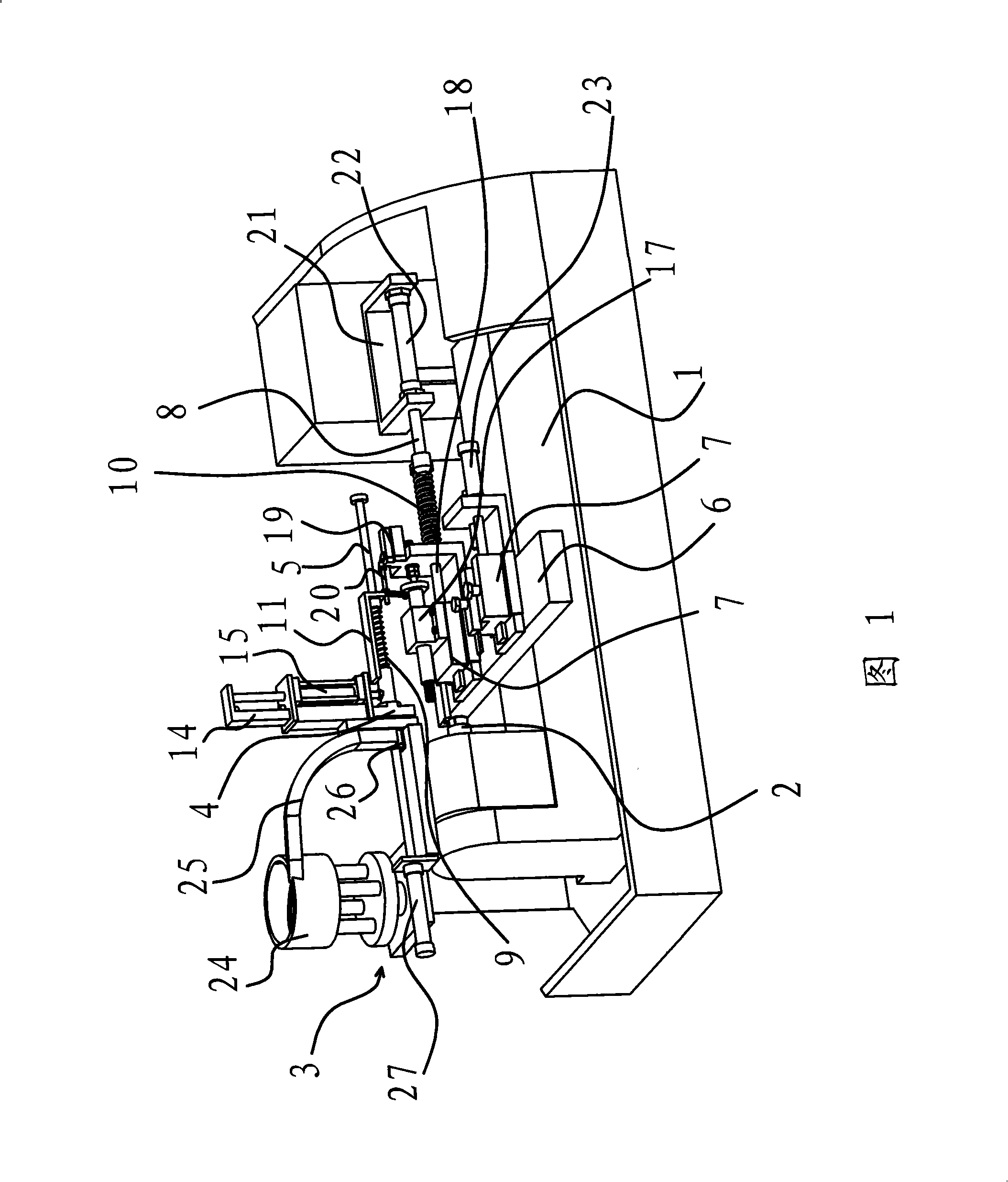
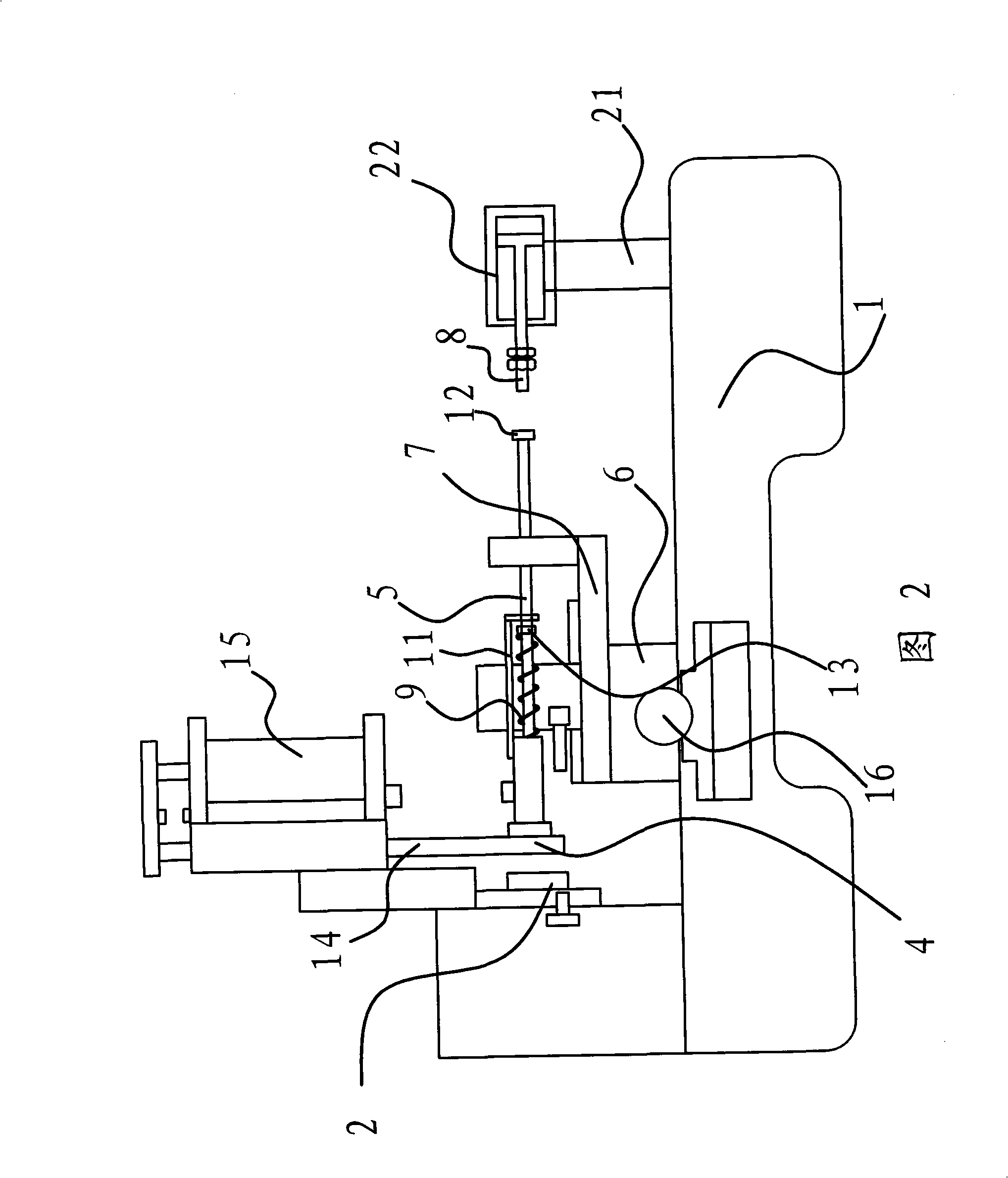
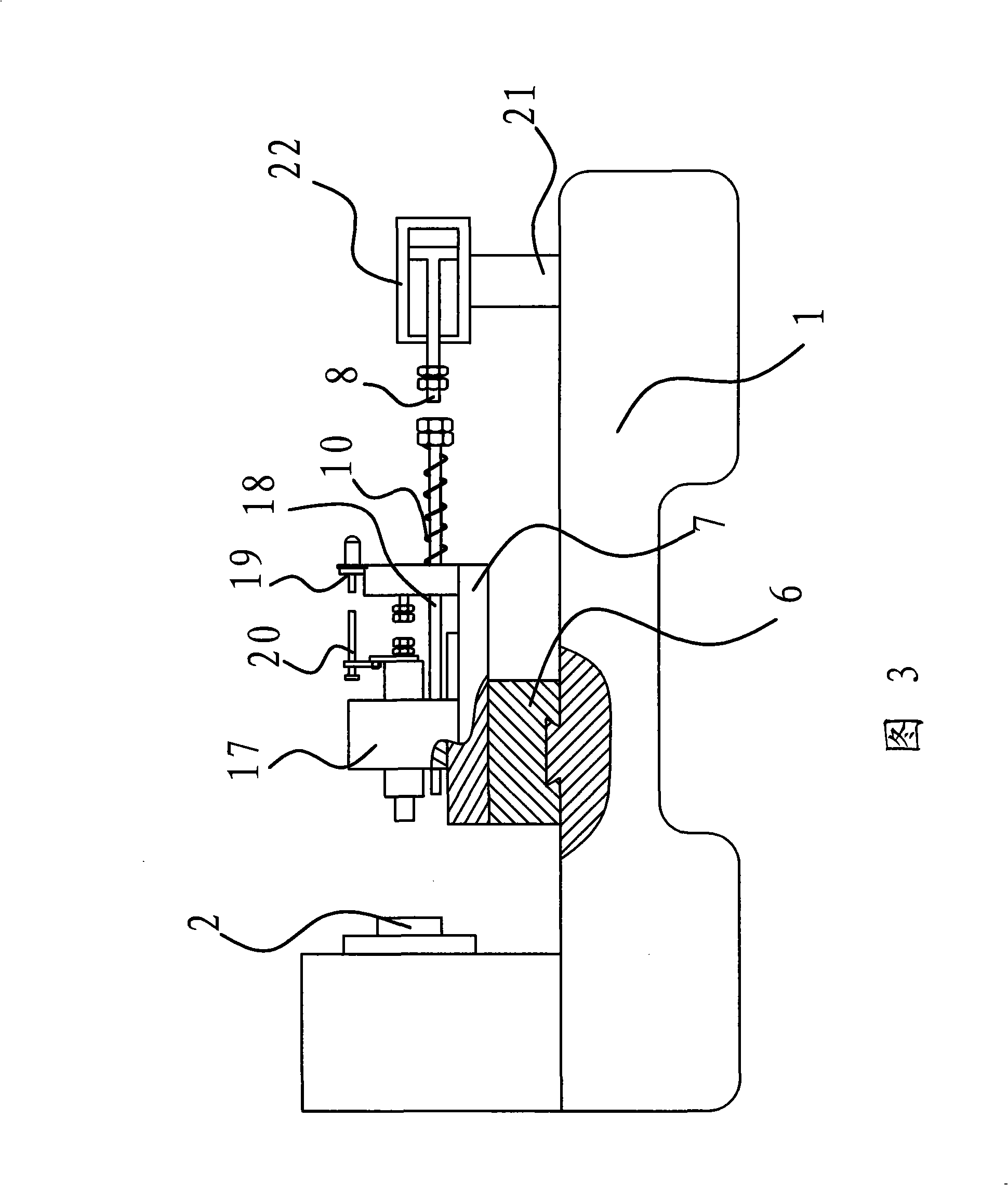
[0026] As shown in Figure 1, Figure 2 and Figure 3, the lathe includes machine base 1, fixture 2, workpiece feeding device 3, material receiving pipe 4, push rod 5, horizontal support plate 6, vertical support plate 7, cutter, top Rod 8, transfer mechanism, return spring one 9 and return spring two 10, etc., to realize the automatic processing of workpieces.

[0027] Specifically, the clamp 2 and the workpiece feeding device 3 are arranged on the machine base 1, and a material receiving tube 4 that can move between the clamps 2 and the workpiece feeding device 3 is provided, and the material receiving tube 4 is fixedly connected On the transfer mechanism, a push rod 5 that can push the workpiece in the material receiving t...


PUM


Abstract

The invention provides a machine tool, which belongs to the technical field of machinery. The machine tool solves the technical problems that a lathe has higher cost and a complicated structure and so on. The lathe comprises a stand, a fixture, a workpiece feeding device, a loading pipe, a push rod, a longitudinal splint, and a cutter, wherein the stand is provided with a post rod which is connected with a moving mechanism, the post rod can push the push rod to move towards the fixture when the loading pipe faces to the fixture; a reset spring 1 of which both ends act on the push rod and the loading pipe respectively is sleeved outside the push rod, and the post rod can push the cutter to move towards the inside of the fixture when the cutter faces to the fixture; and a reset spring 2 which ensures that the cutter exits from the fixture is arranged between the longitudinal splint and a transverse splint. The machine tool has the advantages of saving partial power source, reducing manufacturing cost of machine tools, optimizing structures of the machine tools, having high qualification rate of processed workpieces and so on.

Description

technical field [0001] The invention belongs to the technical field of machinery and relates to a lathe, in particular to a lathe. Background technique [0002] Ordinary instrument lathes for turning, tapping and threading the inner hole of the workpiece are all done manually. The fixture of this common lathe has the functions of rotation and clamping, and the tool is arranged on the carriage under the front and bottom of the fixture. Turn off the motor that drives the jig to rotate, the jig stops rotating, put the workpiece into the jig and clamp it, and then turn on the motor to drive the jig to rotate, thereby driving the workpiece to rotate. The supporting plate is arranged on the guide rail and connected with the cylinder, and the supporting plate is driven by the cylinder to move back and forth, left and right. The pallet is moved so that the tool set on the pallet is close to the workpiece and the workpiece is turned and tapped. [0003] In this kind of ordinary in...

Claims


Application Information

Patent Timeline
Patent Type & Authority Applications(China)
IPC IPC(8): B23B13/02B23B13/10B23B17/00B23Q5/00
Inventor 陈云法
Owner ZHEJIANG SHUANGZHENG MACHINE TOOL CO LTD
Why Eureka
Try Eureka