
High-thrust short-travel voice coil motor

A technology of voice coil motor and short stroke, which is applied in the direction of electrical components, electromechanical devices, etc. It can solve the problems of thrust fluctuation and small thrust of voice coil motor, so as to reduce the volume of the yoke, increase the average thrust, and increase the magnetic density of the air gap Effect

Active Publication Date: 2009-04-08
HARBIN INST OF TECH
View PDF0 Cites 19 Cited by
  • Summary
  • Abstract
  • Description
  • Claims
  • Application Information

AI Technical Summary

Problems solved by technology

[0004] In order to solve the shortcomings of the existing voice coil motors such as small thrust and relatively large thrust fluctuations, the present invention proposes a high-thrust short-stroke voice coil motor

Method used


Image

  • High-thrust short-travel voice coil motor
  • High-thrust short-travel voice coil motor
  • High-thrust short-travel voice coil motor

Examples


specific Embodiment approach 1

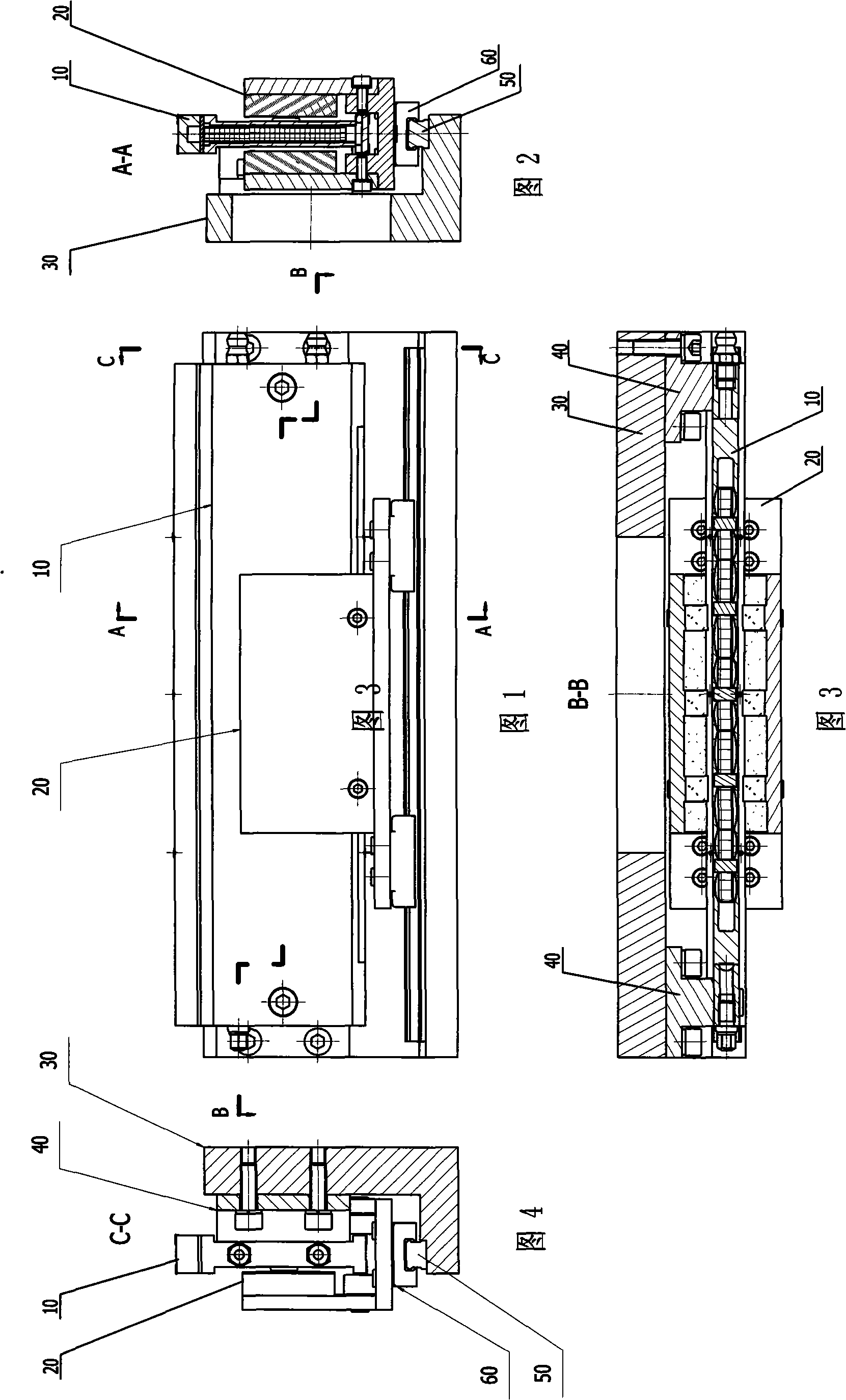
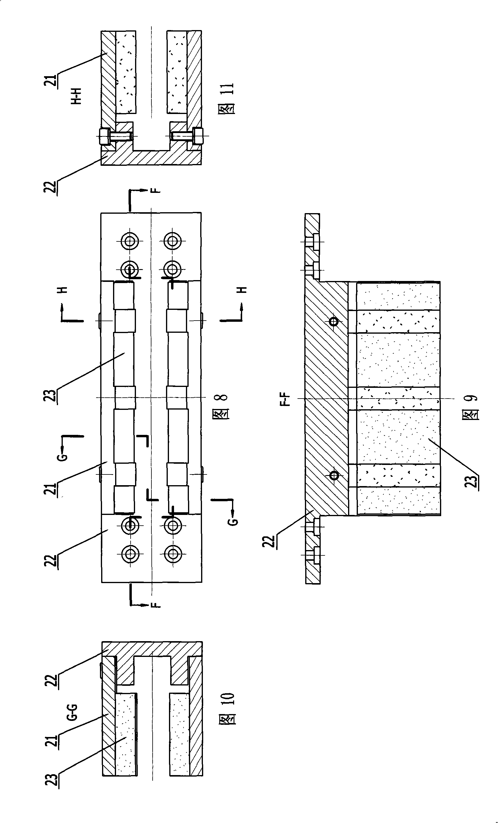
[0009] Specific embodiment one: in conjunction with Fig. 1 to Figure 12 Describe this embodiment, this embodiment is composed of stator 10 , mover 20 , motor base 30 , stator bracket 40 , guide rail 50 and slider 60 .

[0010] The lower platform of the stator support 40 is provided with a guide rail 50, and the slider 60 connected to the guide rail 50 is arranged on the lower bottom surface of the mover 20, the stator 10 is placed in the U-shaped groove of the mover 20, and the two stator supports 40 One end is respectively fixed on the two ends of the stator 10, and the other end of the two stator supports 40 is fixed on the two ends of the vertical plate of the motor base 30, and the stator 10 is supported by the stator supports 40 fixed on the motor base 30. The sub 20 is supported by two slide blocks 60 fixed on the guide rail 50 of the motor base 30 . When the coil in the stator 10 is energized, it is subjected to the electromagnetic force of the magnet steel of the move...

specific Embodiment approach 2

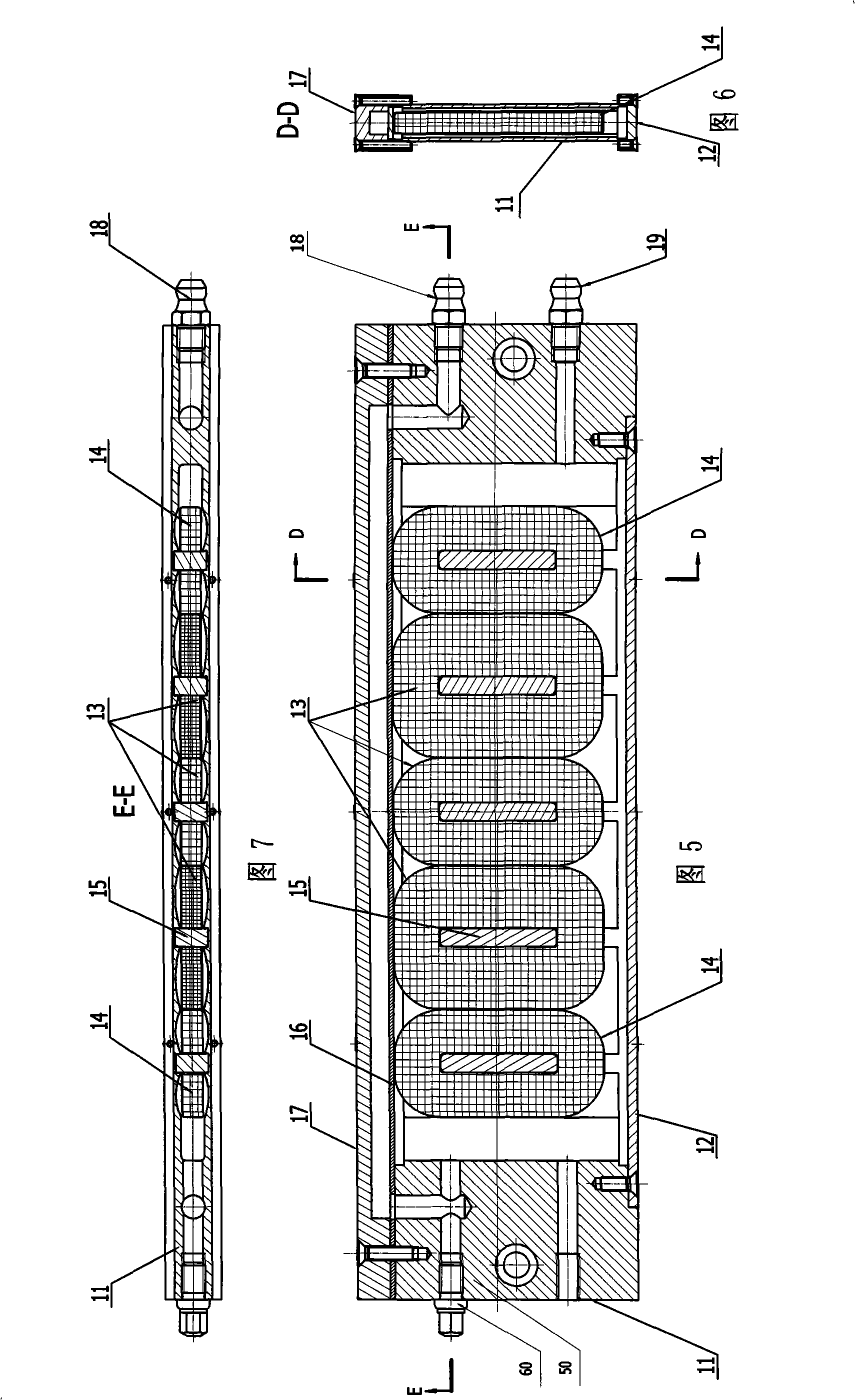
[0014] Specific embodiment 2: This embodiment is described in conjunction with Fig. 5 to Fig. 7. The difference between this embodiment and specific embodiment 1 is that the stator 10 also includes a stator lower cover 12, a stator upper cover gasket 16, and a stator upper cover 17. , water outlet 18 and water inlet 19; stator lower cover plate 12, stator upper cover plate gasket 16, stator upper cover plate 17, water outlet 18 and water inlet 19 are arranged on the stator coil frame 11, and the stator coil of the stator coil is placed The channels of the frame 11 are connected, the stator lower cover plate 12 is arranged on the bottom of the channel of the stator coil frame 11 and is airtightly connected with the stator coil frame 11, the stator upper cover plate gasket 16 and the stator upper cover plate 17 are arranged on the stator coil frame The top of the channel of 11 is airtightly connected with the stator coil frame 11, and a sealed cooling chamber is formed by the sta...

specific Embodiment approach 3

[0015]Specific embodiment three: The difference between this embodiment and specific embodiment one is that the stator coil 13 and the stator additional coil 14 have adopted alcohol-soluble self-adhesive enameled wire, and when winding the coil, smear the alcohol with a concentration of 90%, and put it into an electric oven Heating and setting reduces the volume of the coil skeleton. Other compositions and connection methods are the same as those in Embodiment 1.


PUM


Abstract

The invention discloses a high thrust short stroke voice coil motor and relates to the motor field, solving the defects of low thrust, relatively large thrust fluctuation and the like, in the existing voice coil motors. Two stator interpole coils of the motor are arranged at the two sides of three stator coils and fixed in the groove of a coil rack by a positioning key, the five coils are connected in series; the magnetic steel of a active cell of the motor adopts the structure of bilateral series permanent magnet and consists of the magnetic steels with three different lengths, and the magnetic steels with the first length, the third length and the second length are sequentially arranged towards two sides by taking the middle first steel with the third length as the symmetry axis; along magnetizing direction, the distribution takes Halbach array structure; the length relation between the magnetic steel and the coil meets the following conditions: s1 is equal to 1<2> plus 2d and s2 is equal to 1<1> plus 2d minus s1 and s3 is equal to 1<3> minus 2d. The invention is mainly applied to accurate positioning servo systems, improves the thrust of unit volume and the reliability of the voice coil motor and reduces thrust fluctuation as well as the heat radiation toward the external environment.

Description

technical field [0001] The invention relates to the field of motors, in particular to precise positioning of voice coil motors. Background technique [0002] Voice coil motor is a short-stroke DC linear motor, which is characterized by simple structure, small size, small thrust fluctuation, high acceleration, and fast response. Compared with rotary motors, linear motion can be realized without an intermediate conversion link (ball screw), which reduces costs and improves positioning accuracy; compared with traditional AC linear motors, it has no cogging effect and can achieve better positioning effects. [0003] Based on the above characteristics, voice coil motors are mainly used for precise positioning servo systems, such as lens leveling and focusing, computer hard disk head positioning, and lithography machine macro and micro positioning systems. However, with the development of technology, the technical requirements for voice coil motors are more stringent. For exampl...

Claims


Application Information

Patent Timeline
IPC IPC(8): H02K33/18
Inventor 李立毅潘东华寇宝泉吴红星
Owner HARBIN INST OF TECH
Learn More