Three-wire system high-power LED driver

A LED driver and high-power technology, which is applied in semiconductor devices of light-emitting elements, lighting devices, light sources, etc., can solve problems such as weakening impact, and achieve the effect of avoiding current impact and avoiding current impact

Inactive Publication Date: 2009-04-08
江阴旺达电子有限公司
View PDF4 Cites 7 Cited by
  • Summary
  • Abstract
  • Description
  • Claims
  • Application Information

AI Technical Summary

Problems solved by technology

exist figure 1 In the application, the biggest problem is: the "control switch" (in series with the load) is connected to the secondary (output terminal) of the driver
This solution can only reduce the shock, but cannot completely avoid it

Method used


Image

  • Three-wire system high-power LED driver
  • Three-wire system high-power LED driver
  • Three-wire system high-power LED driver

Examples


Embodiment Construction

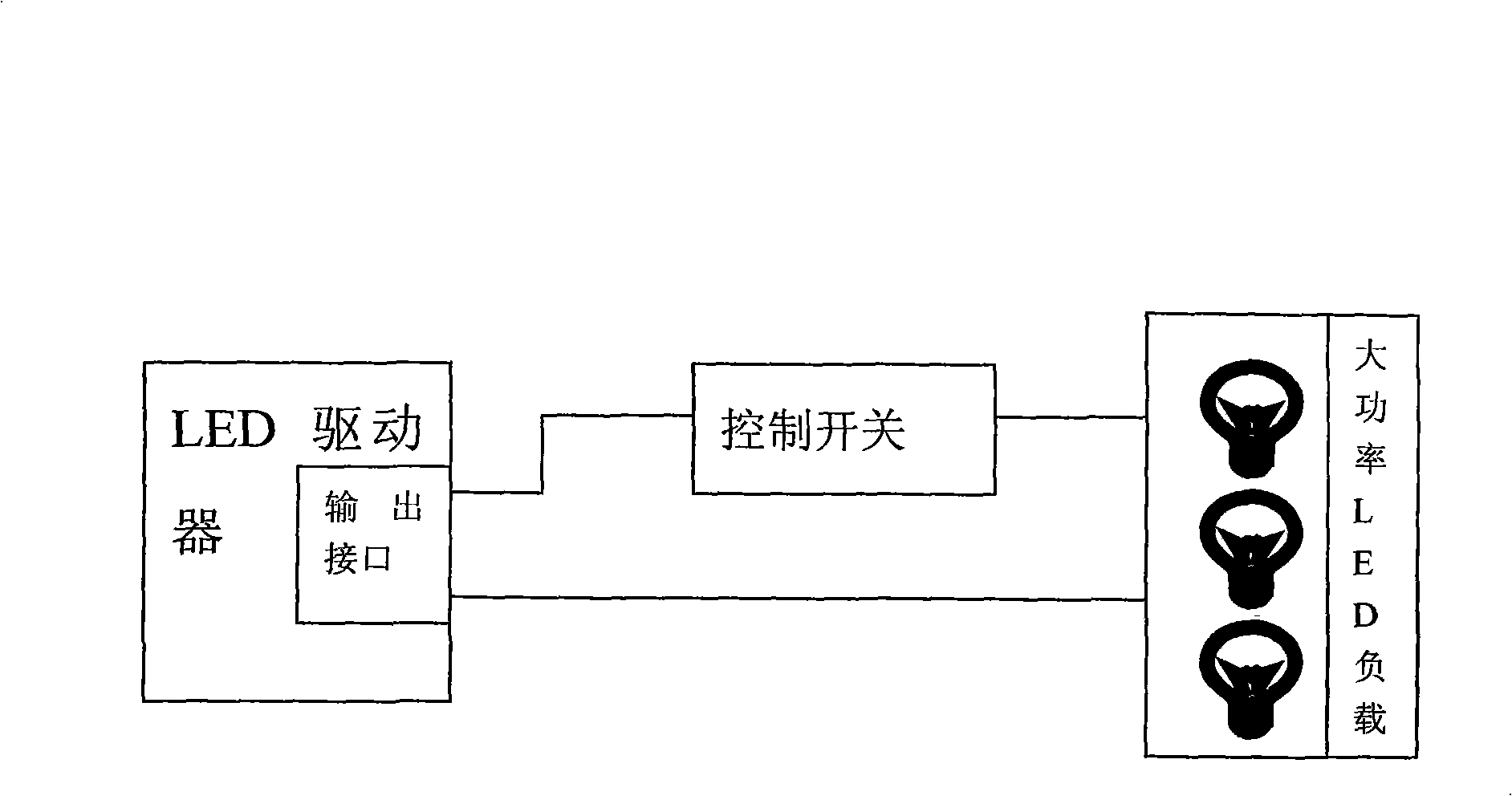
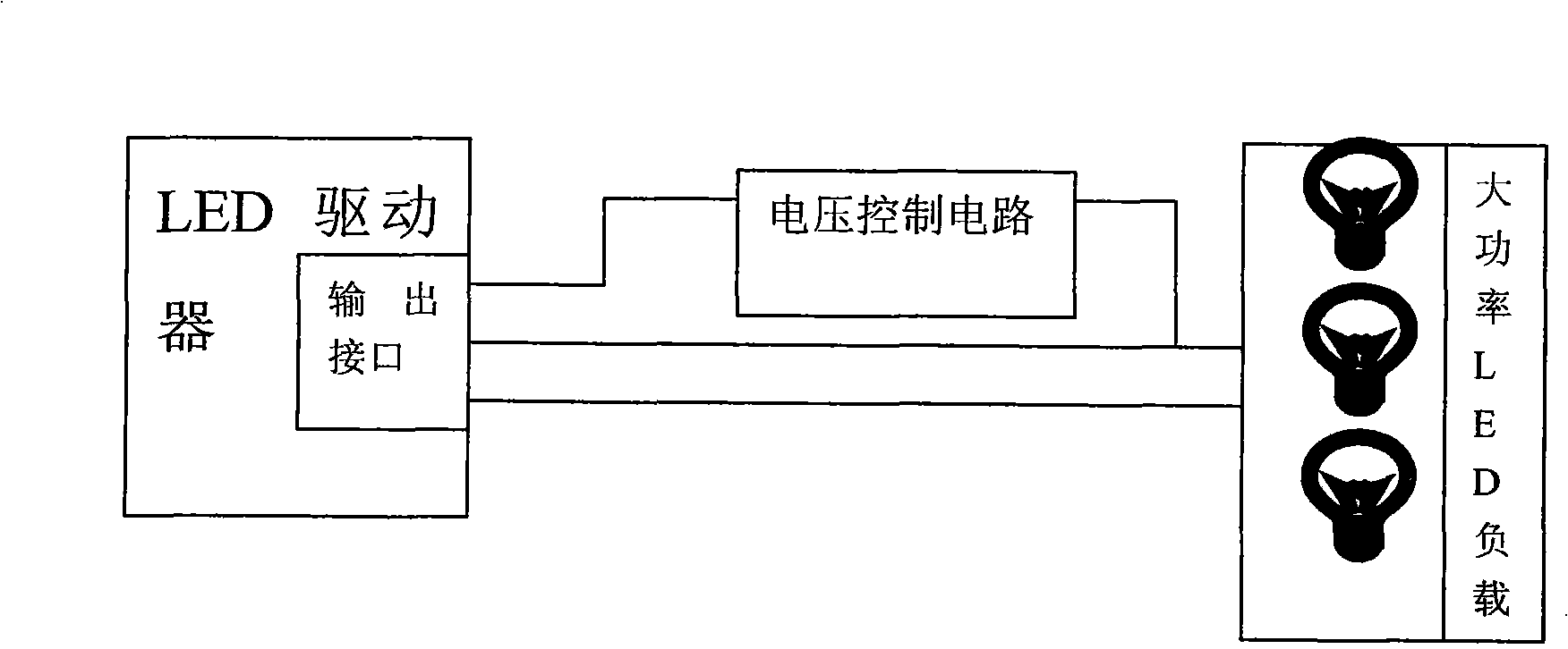
[0020] see image 3 The "voltage control circuit" of the three-wire high-power LED driver of the present invention is a switch circuit, which can form a closed loop with one of the original two output lines, and can control the size of the voltage output. The "output interface" is changed from the original "two-core wire" to "three-core wire". When the light source is turned on, the closed loop is tried to be disconnected, and the output voltage starts to climb upwards from the initial 2V, thus avoiding the impact of the driver on the LED (the impact occurs when the impact is converted from a higher voltage to a lower voltage). When the output current of the driver reaches the set value, the output voltage of the driver reaches a steady state.

[0021] see image 3 ~4. The three-wire high-power LED driver of the present invention has three output lines, which are respectively "output positive terminal", "output negative terminal" and "signal control line", "S1" is the contro...


PUM


Abstract

The invention relates to a three-wire high power LED drive which is mainly used for driving a high power LED. The three-wire high power LED drive comprises an LED drive and a high power LED load and is characterized in that the LED drive is provided with three output wires which are an output anode, an output cathode and a signal control wire respectively. The high power LED load is connected between the output anode and the output cathode. S1 is a control switch. One end of the S1 is connected with the output anode, and the other end thereof is connected with the signal control wire. The signal control wire is connected with a diode anode in an LED drive opto-coupler U2 by a current-limiting resistor R10. The control switch S1, the signal control wire and the current-limiting resistor R10 form a low voltage control circuit together. The three-wire high power LED drive can effectively avoid the problem of current surge when the control switch is closed.

Description

(1) Technical field [0001] The invention relates to a high-power LED driver. It is mainly used to drive high-power LEDs. It belongs to the technical field of electronic products. (2) Background technology [0002] Before the present invention was made, the application block diagram of the driver used for desk lamp type high-power LED in the past was as follows: figure 1 shown. In the customer's current application, the "control switch" and the high-power LED load are used in series, and the number of LED loads is variable, which may be one, two, or three. It creates the following problems: [0003] The LED load is indeterminate. When one LED is turned on, the driver only needs to output 3.5V, and when three LEDs need to be turned on, the driver needs to output 10.5V (3.5V*3), which requires the driver to automatically adjust the output voltage according to the number of loads . In order to ensure that 3 LEDs can be effectively driven, the maximum output voltage of the...

Claims


Application Information

Patent Timeline
Patent Type & Authority Applications(China)
IPC IPC(8): H05B37/02F21V23/00F21Y101/02F21Y115/10
Inventor 赵建洪李剑廖鑫明
Owner 江阴旺达电子有限公司
Why Eureka
Try Eureka