
Brake with drum type floating brake shoe bidirectional propulsion structure

A technology of brakes and brake shoes, which is applied in the direction of mechanically driven drum brakes, brake actuators, brake parts, etc., can solve the problems of uneven force on the brake hub, rising temperature, and reducing vehicle speed, etc., to achieve Eliminate driving safety hazards, uniform temperature rise, and increase the effect of contact area

Inactive Publication Date: 2010-07-28
谭富春
View PDF5 Cites 0 Cited by
  • Summary
  • Abstract
  • Description
  • Claims
  • Application Information

AI Technical Summary

Problems solved by technology

The brake shoes in the brake hub can basically only deflect along the radial direction of the brake hub during braking, push and press the friction plate to contact the inner working surface of the brake hub, and generate friction to make the brake hub rotate faster. reduce the speed of the vehicle to achieve the effect of reducing the speed of the vehicle; the brake shoe cannot move in the brake hub, but can only deflect in the brake hub, so the contact area between the brake shoe and the inner working surface of the brake hub is between the brake shoe and the When the brake hub is concentric and the gap is small, its contact area can only reach 70-80%. When the brake shoe is not concentric with the brake hub and the gap is large, its contact area is only 20-30%. Reduce the brake shoe. The friction force with the inner working surface of the brake hub and the generated friction force cannot evenly act on the brake hub, resulting in uneven force on the brake hub and uneven temperature rise during braking, which affects the brake shoe. The wear is also uneven, etc.; in addition, the fixed end of the brake shoe basically cannot be in contact with the inner working surface of the brake hub, and basically no wear will occur. The inner surfaces of the brake hub are in contact with each other, wear quickly, the temperature rises, and it is easy to wear or thermal fatigue and fail, which significantly reduces its service life, causing the brake hub to be broken due to uneven force, and there is also a safety hazard of brake failure

Method used


Image

  • Brake with drum type floating brake shoe bidirectional propulsion structure
  • Brake with drum type floating brake shoe bidirectional propulsion structure
  • Brake with drum type floating brake shoe bidirectional propulsion structure

Examples


Embodiment Construction

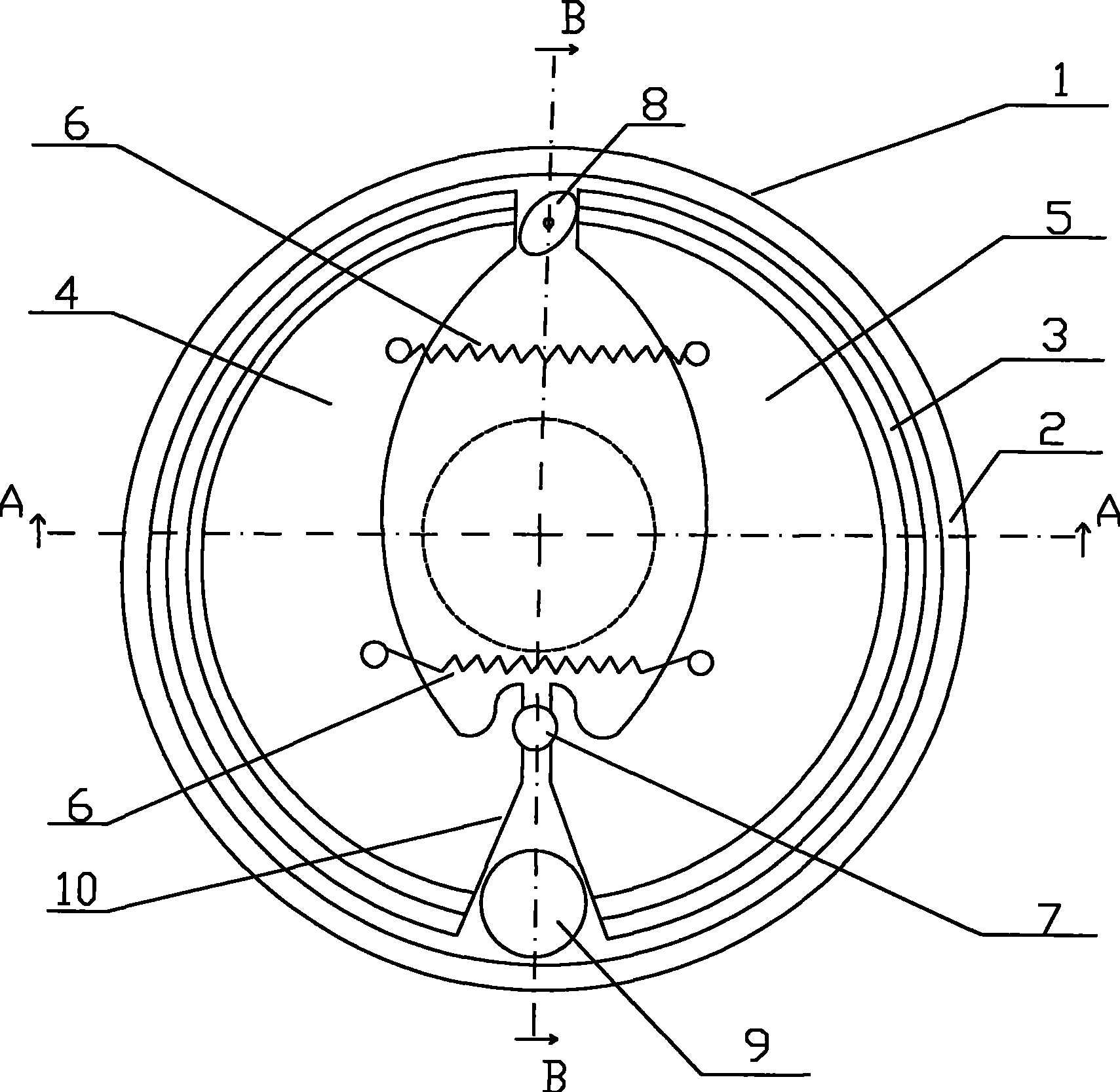
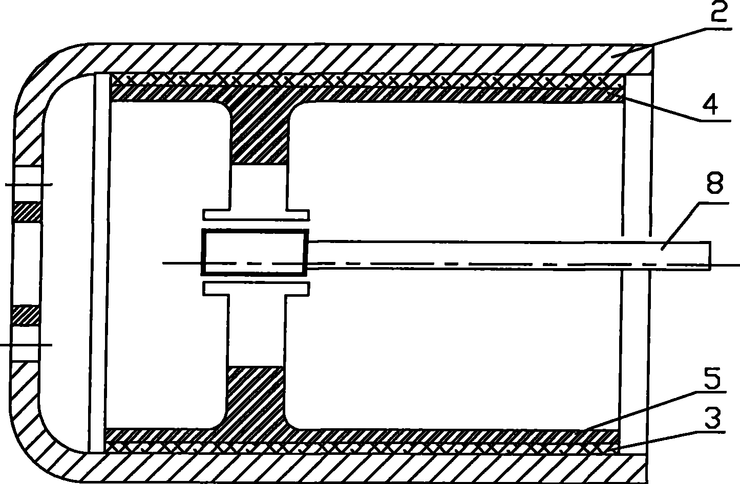
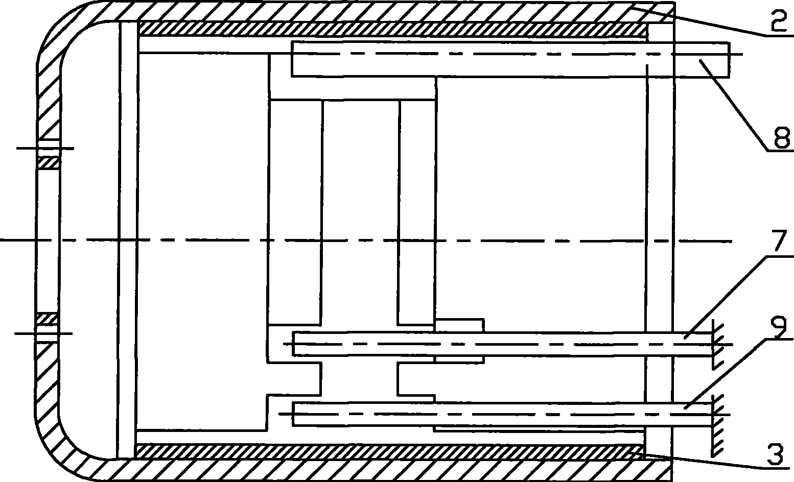
[0016] Such as figure 1 , 2 , 3, 1—brake body, 2—brake hub, 3—friction plate, 4—left brake shoe, 5—right brake shoe, 6—extension spring, 7—hinge column, 8—cam, 9—garden pin, 10—inclined plane;

[0017] The drum-type floating brake shoe bidirectional push structure brake of the present invention includes a brake body 1, and the brake body 1 is mainly composed of a circular brake hub 2, a friction plate 3, a left brake shoe block 4, a right brake shoe block 5, The hinge column 7 and the cam 8 are composed, and the left brake shoe 4 and the right brake shoe 5 are provided with friction plates 3 (usually connected by riveting), and the left brake shoe 4 and the right brake shoe 5 The friction plate 3 is in contact with the inner working surface of the brake hub 2, and the left brake shoe 4 and the right brake shoe 5 are arranged in the inner cavity of the circular brake hub 2; the left brake shoe 4 and the right brake shoe Extension springs 6 are arranged between the moving sho...


PUM


Abstract

The invention discloses a drum-typed floating brake shoe bi-direction pushing structure brake which comprises a brake body which comprises a bake hug, a friction plate, a left brake shoe block, a right brake shoe block and a tension spring. The left brake shoe block and the right brake shoe block are movably connected by a hinge pillar. The brake is characterized in that: a cam is arranged at theother side opposite to the hinge pillar and between the left brake shoe block and the right brake shoe block; a round pin is arranged at the side of the hinge pillar and between the left brake shoe block and the right brake shoe block; and the position, at which the left brake shoe block and the right brake shoe block are matched with the round pin is an inclined plane. In the brake of the invention, both the coupling ends and the movable ends of the brake shoe blocks are outward stretched, thus increasing the contacting area between the brake shoe blocks and the inner side surface of the brake hub and keeping the contacting area to be unchanged; the brake ensures uniform brake and uniform temperature rising caused by braking, can reduce the abrasion of the brake hub, cause difficult fracture of the brake hub, prolong the service life of the brake hug, eliminate traffic safety hidden trouble, and ensure safety.

Description

technical field [0001] The invention relates to a brake for vehicle braking, especially a drum type, floating, two-way pushing brake with brake shoes. Background technique [0002] Brakes play a very important role in ensuring driving safety. The drum brake used for vehicle braking is composed of a brake hub, left and right brake shoes, cams, hinge columns, etc. The left and right brake shoes are installed in the brake hub, and one end is fixed on the hinge column and can rotate around the hinge column. The other end leans against the cam, and the rotation of the cam pushes the left and right brake shoes to rotate around the hinge column to both sides, pushes and presses the friction plate to contact the inner working surface of the brake hub, and generates friction to reduce the speed of the brake hub, achieving a reduction The effect of vehicle speed; to slow down or stop the vehicle to ensure the safe operation of the vehicle; there are many types of brakes in the prior ...

Claims


Application Information

Patent Timeline
Patent Type & Authority Patents(China)
IPC IPC(8): F16D51/22F16D65/09F16D65/18
Inventor 谭富春
Owner 谭富春
Learn More