Rope checking method
An inspection method and rope technology, applied to electromagnetic measuring devices, elevators, instruments, etc., can solve the problems of wire rope detector damage, long inspection time, and reduced wire rope speed
- Summary
- Abstract
- Description
- Claims
- Application Information
AI Technical Summary
Problems solved by technology
Method used
Image

Examples
Embodiment approach 1
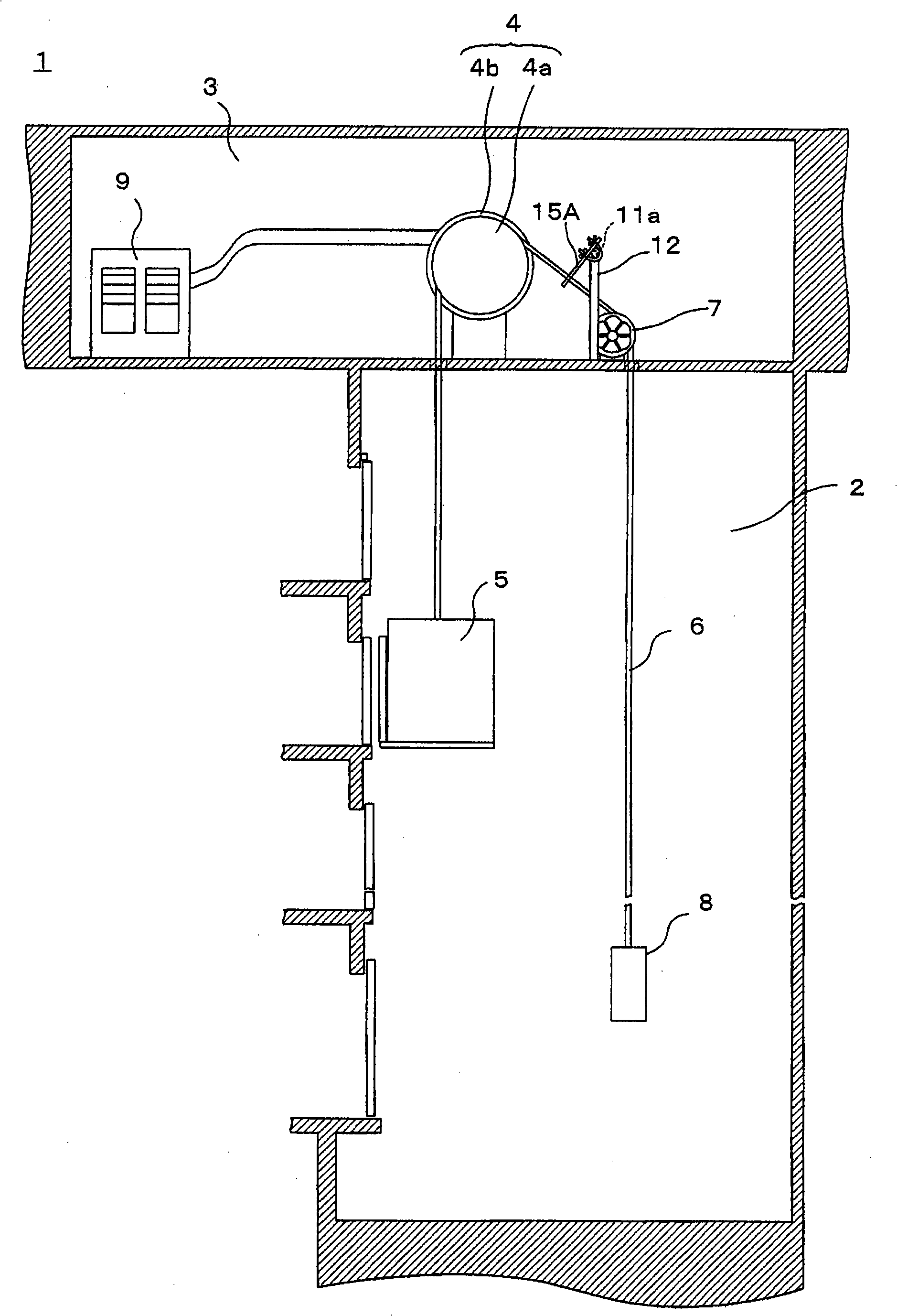
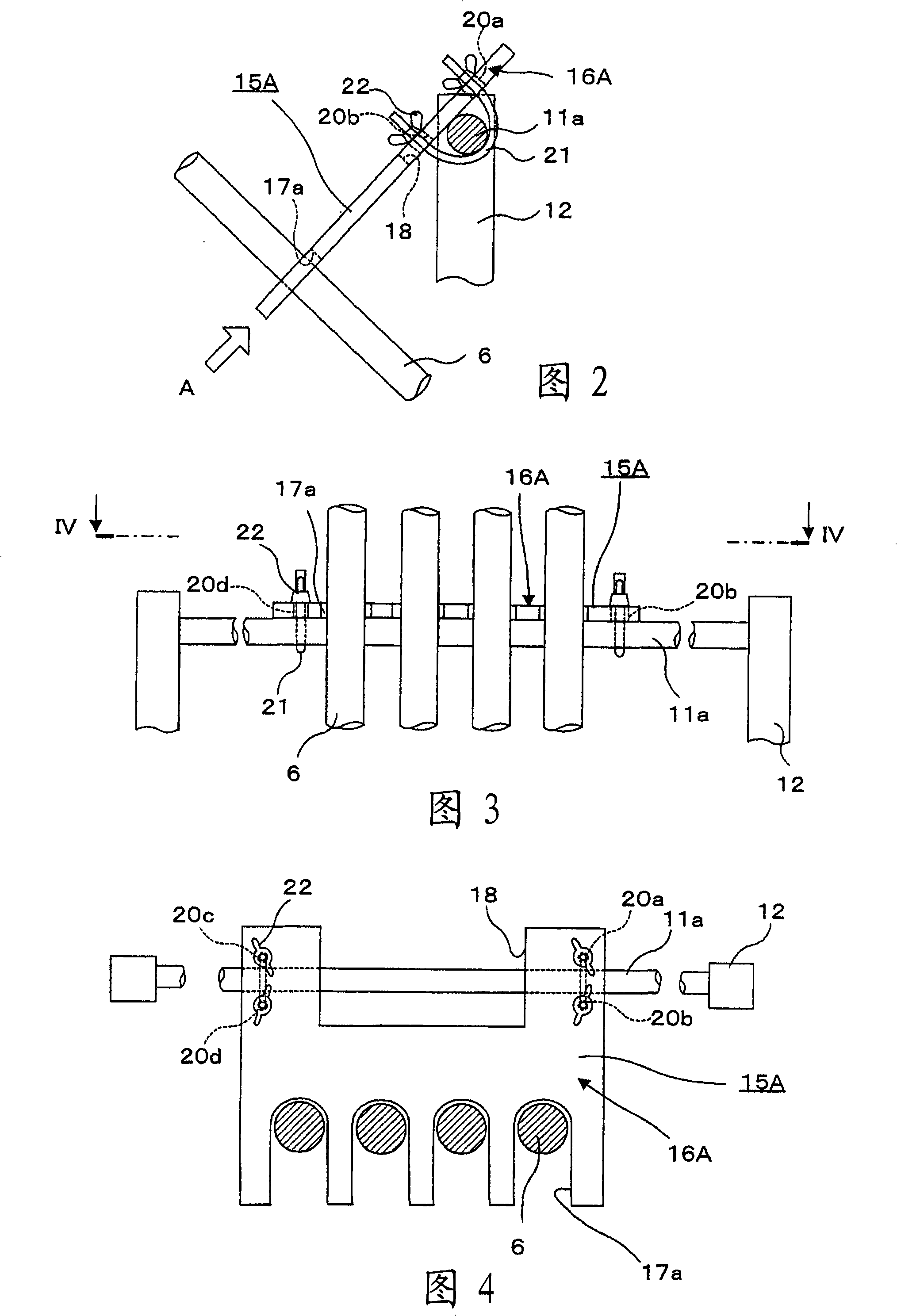
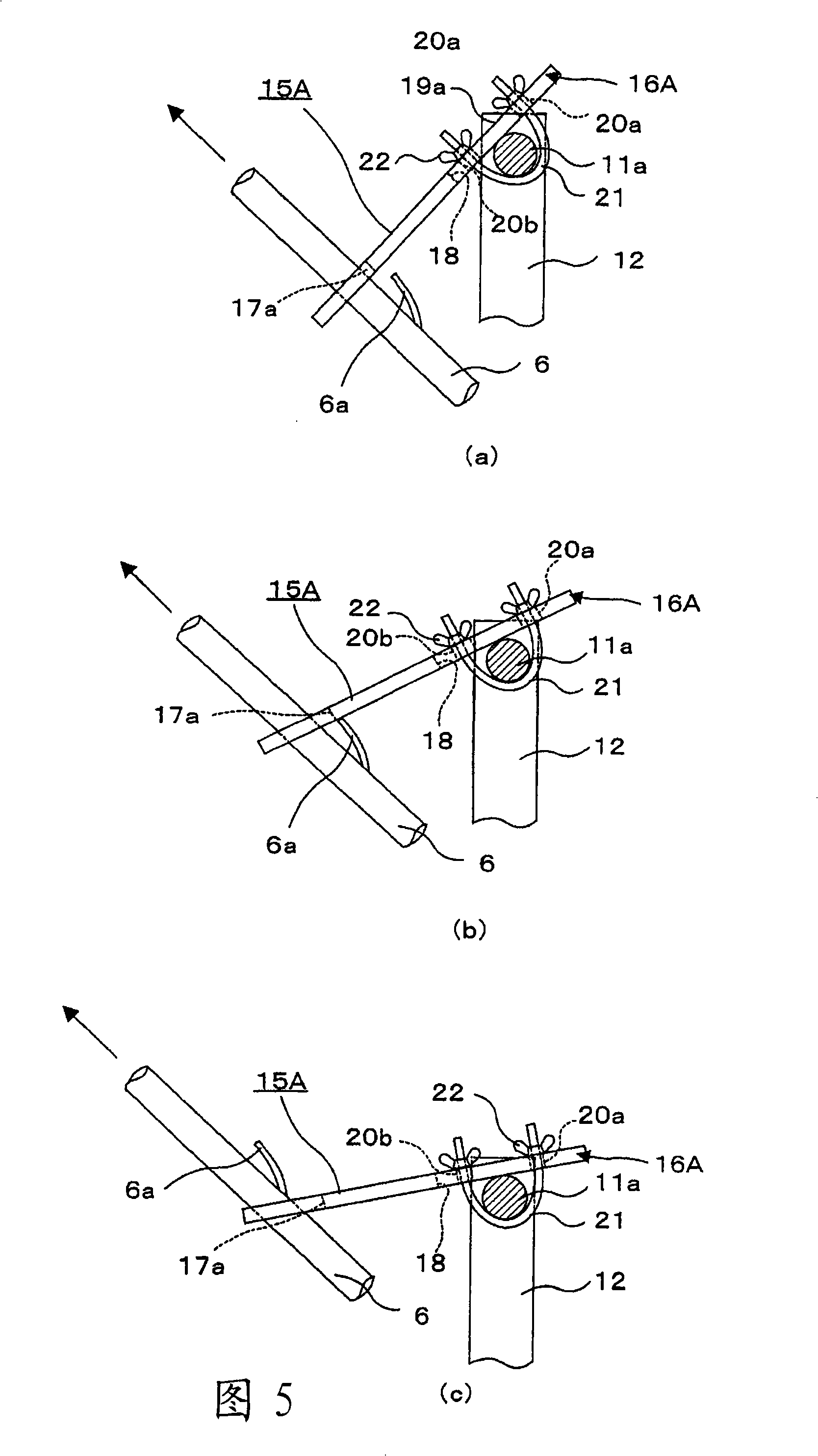
[0027] figure 1 It is a schematic diagram of an elevator having a wire rope inspected by the rope inspection method according to Embodiment 1 of the present invention; FIG. 2 is a side view of a protruding abnormality detection device used in the preliminary inspection of the rope inspection method according to Embodiment 1 of the present invention ; Fig. 3 is a front view of A direction in Fig. 2; Fig. 4 is a cross-sectional view viewed along the IV-IV arrow in Fig. 3; The side view of the protruding abnormality detection device in the detection process of the protruding abnormality of the wire rope, Fig. 5(a) to Fig. 5(c) show the action of the detection piece when the protruding part of the wire rope passes through the installation position of the detection piece. Image 6 It is an external view of a rope tester used in the main inspection of the rope inspection method according to Embodiment 1 of the present invention; Figure 7 is along Image 6 The cross-sectional view...
Embodiment approach 2
[0101] Figure 12 It is a plan view of the protruding abnormality detection device used in the preliminary inspection of the rope inspection method according to Embodiment 2 of the present invention.
[0102] In addition, in Figure 12 In , the same reference numerals are assigned to the same or similar parts as those in Embodiment 1, and descriptions thereof will be omitted.
[0103] exist Figure 12In the detection piece 16B of the protruding abnormality detection device 15B, on one side of the detection piece 16B on both sides of the formation part of the detection groove 17a, a wire receiving groove 45 is formed in which the groove direction is consistent with the axial direction of the installation common shaft 11a. . In addition, the detection piece 16B is supported by the attachment common shaft 11a using the attachment member 21 like Embodiment 1 mentioned above.
[0104] At this time, the wire accommodating groove 45 is formed in such a position that when the dete...
Embodiment approach 3
[0112] Figure 13 It is a plan view of the protruding abnormality detection device used in the preliminary inspection of the rope inspection method according to Embodiment 3 of the present invention.
[0113] exist Figure 13 Among them, the protruding abnormality detecting device 15C is constituted by a pair of protruding abnormality detecting device units 50A and 50B.
[0114] Respectively on the detection pieces 16C, 16D of each protruding abnormality detection device monomer 50A, 50B, on each other end side of the detection pieces 16C, 16D, in the length direction of the long sides of the detection pieces 16C, 16D in the direction of the wire rope 6 Four semicircular detection grooves 17 b are formed at uniform intervals. At this time, each detection groove 17b is shaped so as to accommodate half of the outer peripheral surface of the wire rope 6 with a predetermined gap.
PUM
 Abstract
Description
Claims
Application Information
 - R&D
- Intellectual Property
- Life Sciences
- Materials
- Tech Scout
- Unparalleled Data Quality
- Higher Quality Content
- 60% Fewer Hallucinations
Browse by: Latest US Patents, China's latest patents, Technical Efficacy Thesaurus, Application Domain, Technology Topic, Popular Technical Reports.
© 2025 PatSnap. All rights reserved.Legal|Privacy policy|Modern Slavery Act Transparency Statement|Sitemap|About US| Contact US: help@patsnap.com