Hydraulic clamping head of rotating bending drawframe

A technology of hydraulic chuck and stretching machine, applied in the field of hydraulic chuck, can solve the problems of poor and accurate control of clamping force, affecting processing accuracy, unevenness, etc., so as to improve operability and stability, and increase reliability. , the effect of improving the utilization rate

Inactive Publication Date: 2009-04-22
SUZHOU IND PARK ELECTROMECHANICAL EQUIP
View PDF0 Cites 1 Cited by
  • Summary
  • Abstract
  • Description
  • Claims
  • Application Information

AI Technical Summary

Problems solved by technology

During the processing, the plastic deformation of the metal material needs to bear a large tensile force, so the workpiece must be clamped firmly, otherwise the retraction of the metal material will affect the processing accuracy. In the prior art, four oil cylinders are generally used from the upper and lower directions. The main disadvantages of pushing the upper and lower chucks to clamp the workpiece are: first, due to the limitation of the volume, the shape of the chuck should not be too large, so the oil cylinder that provides power must also be reduced in size, so the clamping force of the chuck is will be limited. In addition, multiple oil cylinders act together on the workpiece, and the clamping force is not easy to control accurately and unevenly; second, when the workpiece is stretched, it needs to be kept in a clamped state for a period of time. During this period, it needs to be kept Keep the oil pressure of the oil cylinder at the maximum value of the working pressure, which is a waste of energy and easy to cause damage to the chuck

Method used


Image

  • Hydraulic clamping head of rotating bending drawframe
  • Hydraulic clamping head of rotating bending drawframe
  • Hydraulic clamping head of rotating bending drawframe

Examples


Embodiment Construction

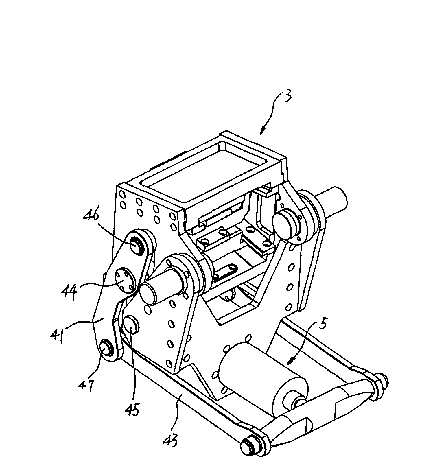
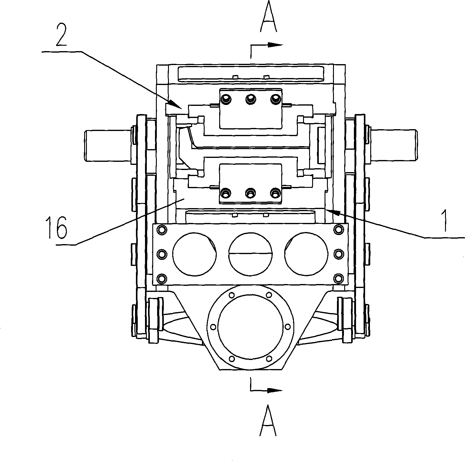
[0024] See attached figure 1 to attach figure 2 As shown, a hydraulic chuck of a rotary bending stretching machine includes a chuck body 3, an upper chuck 2 fixedly arranged on the chuck body 3, and a movable chuck body 3. The lower chuck 1, the chuck body 3 is provided with a connecting rod group 4, the connecting rod group 4 is connected with the lower chuck 1, and the lower chuck 1 moves up and down through the movement of the connecting rod group 4, so as to achieve clamping or loosening The purpose of the artifact.

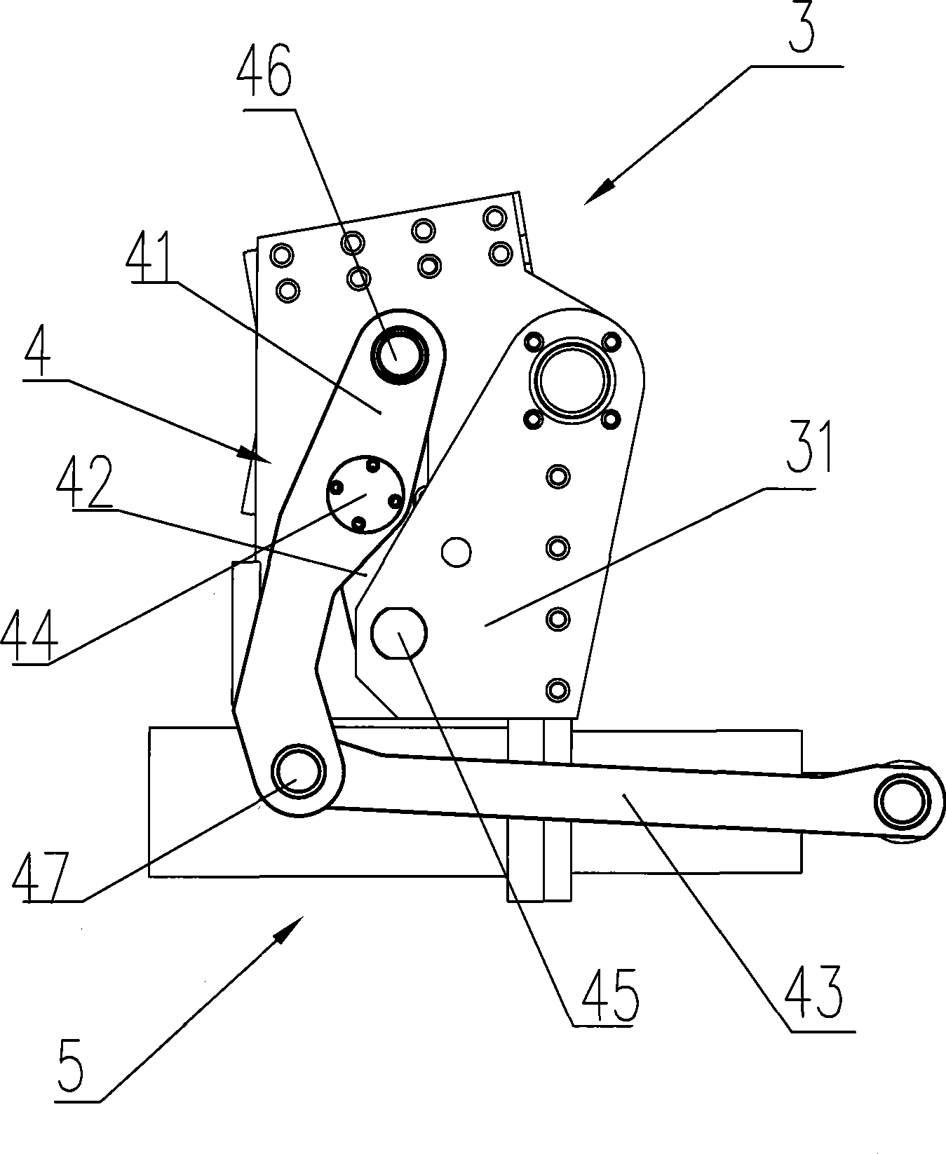
[0025] The connecting rod group 4 is mainly composed of a connecting rod plate 42, a main rocker arm 41 and a long connecting rod 43. The connecting rod plate 42 is rotatably connected to the chuck main body 3 through a first rotating shaft 45, and the main rocking arm 41 is connected through a second rotating shaft. 44 is rotatably connected to the link plate 42, one end of the main rocker arm 41 is connected to the lower chuck 1 through the third rotatin...


PUM


Abstract

The invention belongs to the field of calendaring equipment, and particularly relates to a hydraulic clip head for a rotary bending stretcher. The hydraulic clip head comprises a clip head main body, an upper clip head in fixed arrangement, and a lower clip head in moving arrangement, wherein the clip head main body is in rotary connection with a connecting rod plate through a first rotary shaft, the connecting rod plate is in rotary connection with a main rocking arm through a second rotary shaft, one end part of the main rocking arm is connected with the lower clip head through a third rotary shat, the other end part of the main rocking arm is connected with a power element by a fourth rotary shaft, the clip head main body is provided with a guide groove, the third rotary shaft is inserted in the guide groove in a sliding way, the main rocking arm is provided with a self-locking device, the centers of the first rotary shaft, the second rotary shaft, the third rotary shaft and the fourth rotary shaft are on the same straight line when the main rocking arm is on the self-locking position, and the lower clip head is closely pressed against the upper clip head. The hydraulic clip head has the advantages of reliable use, low maintenance rate, uniform pressing force applied to a work piece, high production efficiency and energy conservation.

Description

technical field [0001] The invention belongs to the field of calendering equipment, in particular to a hydraulic chuck used on a rotary bending and stretching machine. Background technique [0002] Usually, when using a stretching machine to stretch metal materials, it is usually necessary to use the main chuck to clamp one end of the workpiece, the other end of the workpiece is fixed on the mold, and the end clamped by the main chuck moves around the mold to make the workpiece in the mold. produce plastic deformation. During the process of processing, the plastic deformation of the metal material needs to bear a large tensile force, so the workpiece must be clamped firmly, otherwise the retraction of the metal material will affect the processing accuracy. In the prior art, four oil cylinders are generally adopted from the upper and lower directions. The main disadvantages of pushing the upper and lower chucks to clamp the workpiece are: first, due to the limitation of the ...

Claims


Application Information

Patent Timeline
IPC IPC(8): B21D43/00B21D5/06
Inventor 马良吴炯吴宏昌
Owner SUZHOU IND PARK ELECTROMECHANICAL EQUIP
Why Eureka
Try Eureka