
Module type pulse conversion turbocharging system with scaling type exhaust pipe

A technology of turbocharging system and exhaust branch pipe, which is applied to gas turbine devices, machines/engines, internal combustion piston engines, etc., can solve the problems of low turbine efficiency, small exhaust pipe volume, and poor low-load performance of the supercharging system, etc. Achieve the effect of excellent performance, simple structure and reasonable design

Inactive Publication Date: 2009-04-22
SHANGHAI JIAO TONG UNIV
View PDF1 Cites 0 Cited by
  • Summary
  • Abstract
  • Description
  • Claims
  • Application Information

AI Technical Summary

Problems solved by technology

The volume of the exhaust pipe of the pulse supercharging system is small, the entropy increase of the exhaust gas from the exhaust valve to the turbine inlet is small, the exhaust energy utilization rate is high, and the load change can be reflected in time, and the response speed is fast; However, because the turbine is pulsating intake air, resulting in low turbine efficiency, the pulse supercharging system is beneficial for low load and transient conditions
The modular pulse conversion supercharging system combines the advantages of the pulse supercharging system and the constant pressure supercharging system, but the low-load performance of this supercharging system is very poor, and when it is applied to some engines, it will make some cylinder heads Temperature is too high
In the existing technology, the patent number is 97242566.7, which is called the hybrid pulse converter exhaust system utility model patent, which solves the problem that the temperature of some cylinder heads is too high when the engine adopts a modular pulse converter supercharging system, but the low Load performance is still not very good

Method used


Image

  • Module type pulse conversion turbocharging system with scaling type exhaust pipe
  • Module type pulse conversion turbocharging system with scaling type exhaust pipe

Examples


Embodiment Construction

[0009] The specific implementation of the present invention will be further described below in conjunction with the accompanying drawings.

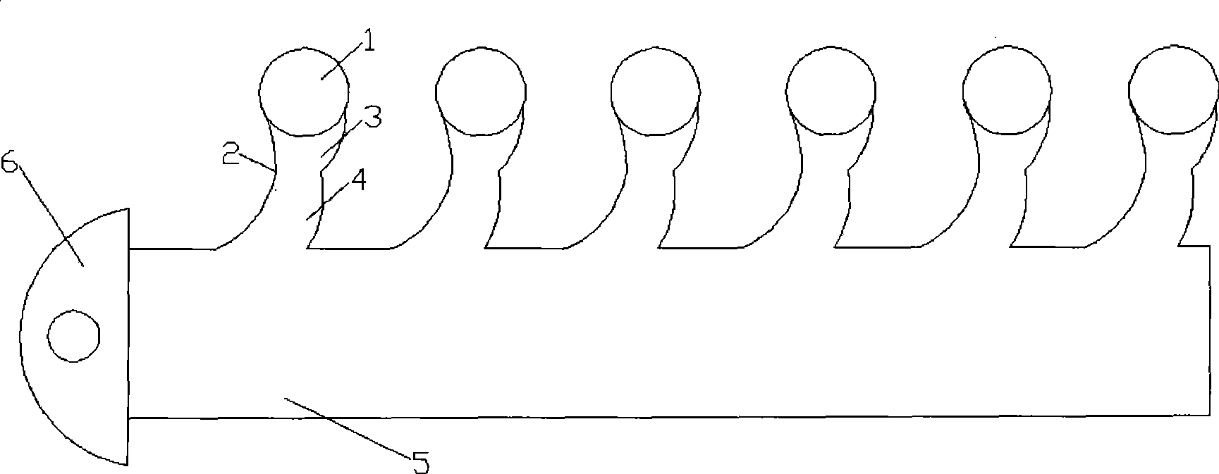
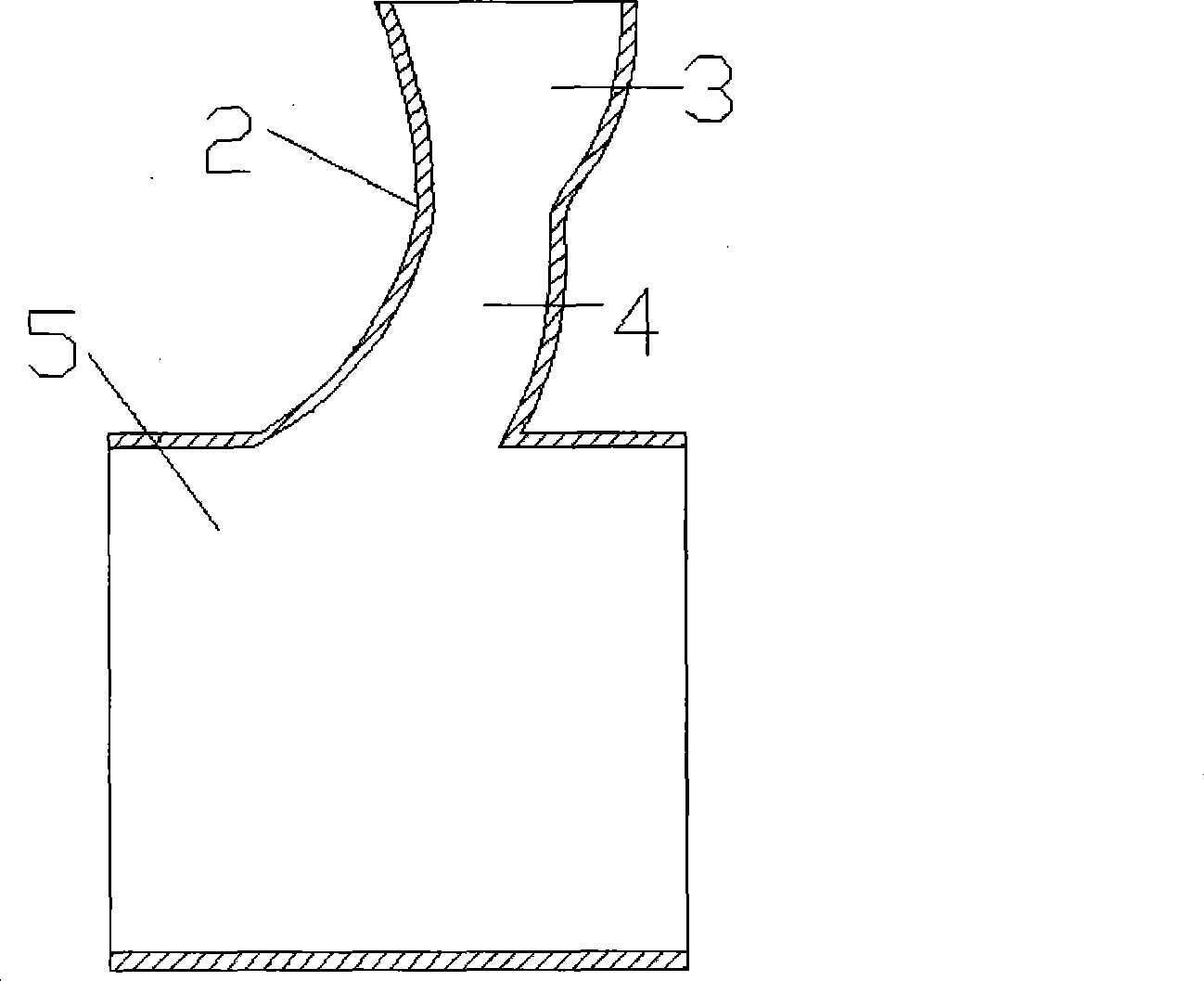
[0010] Such as figure 1 , figure 2 Shown, the present invention comprises cylinder 1, exhaust branch pipe 2, exhaust pipe 5 and turbine 6, and cylinder 1 is connected with exhaust pipe 5 by exhaust branch pipe 2, and turbine 6 is a single inlet, and the outlet of exhaust pipe 5 is connected with exhaust pipe 5. The inlets of the turbine 6 are connected, and the exhaust branch pipe 2 is smoothly connected by a reducer 3 with a gradually reduced cross-sectional area and an expander 4 with a gradually enlarged cross-sectional area. After optimized calculation, the inlet diameter of the reducer 3 and the outlet diameter of the expander 4 are equal, and the ratio of the outlet sectional area of ​​the reducer 3 to the inlet sectional area of ​​the reducer 3 ranges from 0.6 to 0.9. Here, the inlet of the reducer 3 is the inlet of the exhaust ...


PUM


Abstract

The invention relates to a module type pulse conversion turbocharging system with a scaling-type exhaust branch pipe and belongs to the technical field of internal combustion engine. The module type pulse conversion turbocharging system comprises a cylinder, an exhaust branch pipe, an exhaust pipe and a turbine; and the exhaust branch pipe consists of a gradually reducing pipe with gradually reducing sectional area and a gradually increasing pipe with gradually enlarging sectional area in smooth connection. When the engine runs in low load, the exhaust pressure in the gradually reducing pipe can be rapidly risen as the exhaust branch pipe necks down in advance in order to reduce the restriction loss of an exhaust valve and improve the low-load performance of the engine; when the engine runs in high load, the turbocharging system is wholly changed into a module type pulse conversion supercharging system; and the engine has good performance of high load. The module type pulse conversion turbocharging system has the advantages that the module type pulse conversion turbocharging system has reasonable design and a simple structure, can improve the low-load performance of the engine and is suitable for the turbocharging system the turbine of which is provided with a single inlet and laterally arranged.

Description

technical field [0001] The invention relates to a turbocharging system of an internal combustion engine, in particular to a modular pulse conversion turbocharging system in which the turbine is a single inlet and the exhaust branch pipe on the side of the turbine is a scaling type, and belongs to the technical field of the internal combustion engine. Background technique [0002] With the development of society and the improvement of environmental protection requirements, engine boosting technology is now more and more widely used. Most of the medium and high-power engines use turbocharging technology to increase power and reduce fuel consumption. The two basic supercharging systems for turbocharged engines are constant pressure supercharging system and pulse supercharging system. The structural feature of the constant pressure booster system is that the volume of the exhaust pipe is large, the exhaust pipe plays a role in stabilizing the pressure, the fluctuation of the exh...

Claims


Application Information

Patent Timeline
IPC IPC(8): F02B37/00F02C6/12
CPCY02T10/144Y02T10/12
Inventor 王绍明邓康耀崔毅田中旭石磊
Owner SHANGHAI JIAO TONG UNIV
Learn More