One-way constant flow check valve

A check valve, one-way technology, applied in valve details, control valves, safety valves, etc., can solve the problems of increased workload, excessive water flow, and high cost, and achieve the purpose of preventing liquid backflow, reducing volume, and low cost. Effect

Inactive Publication Date: 2009-04-22
吴方忠
View PDF0 Cites 1 Cited by
  • Summary
  • Abstract
  • Description
  • Claims
  • Application Information

AI Technical Summary

Problems solved by technology

[0004] In order to make users feel comfortable, the flushing water used is small, and its on-off is controlled by an electromagnetic flushing valve. However, the tap water pressure in different regions and the tap water pressure in the same region at different times may vary greatly. In addition, for a specific user For example, since multiple water devices share one water inlet pipe as a water source, for example, a user generally only has one water inlet pipe as a water source in his home, but there are multiple faucets in the user's bathroom and kitchen. When the faucet is turned on, the water flow of the faucet in the bathroom may become very small, so that there will often be a phenomenon of "water competition" between multiple water devices, that is, there will be a large change in the water flow flowing out of the water device
If the existing ordinary electromagnetic flushing valve is used to turn on and off the water flow, the flow rate of the water sprayed from the outlet of the electromagnetic flushing valve has a direct linear relationship with the water pressure at the inlet of the electromagnetic flushing valve, and the phenomenon of excessive water flow often occurs. Or the phenomenon that the water flow is suddenly large or small, which will lead to poor washing effect on the human body, directly affect the cleaning effect, and at the same time, the user will feel very uncomfortable
[0005] In addition, in the case of high water pressure, the water flow may flow back in the electromagnetic flushing valve, which will also affect the flushing effect; in order to prevent the water from flowing back, the current common measure is to add a check valve to the pipeline. The cost is high, and it also increases the workload for pipeline installation

Method used


Image

  • One-way constant flow check valve
  • One-way constant flow check valve
  • One-way constant flow check valve

Examples


Embodiment 1

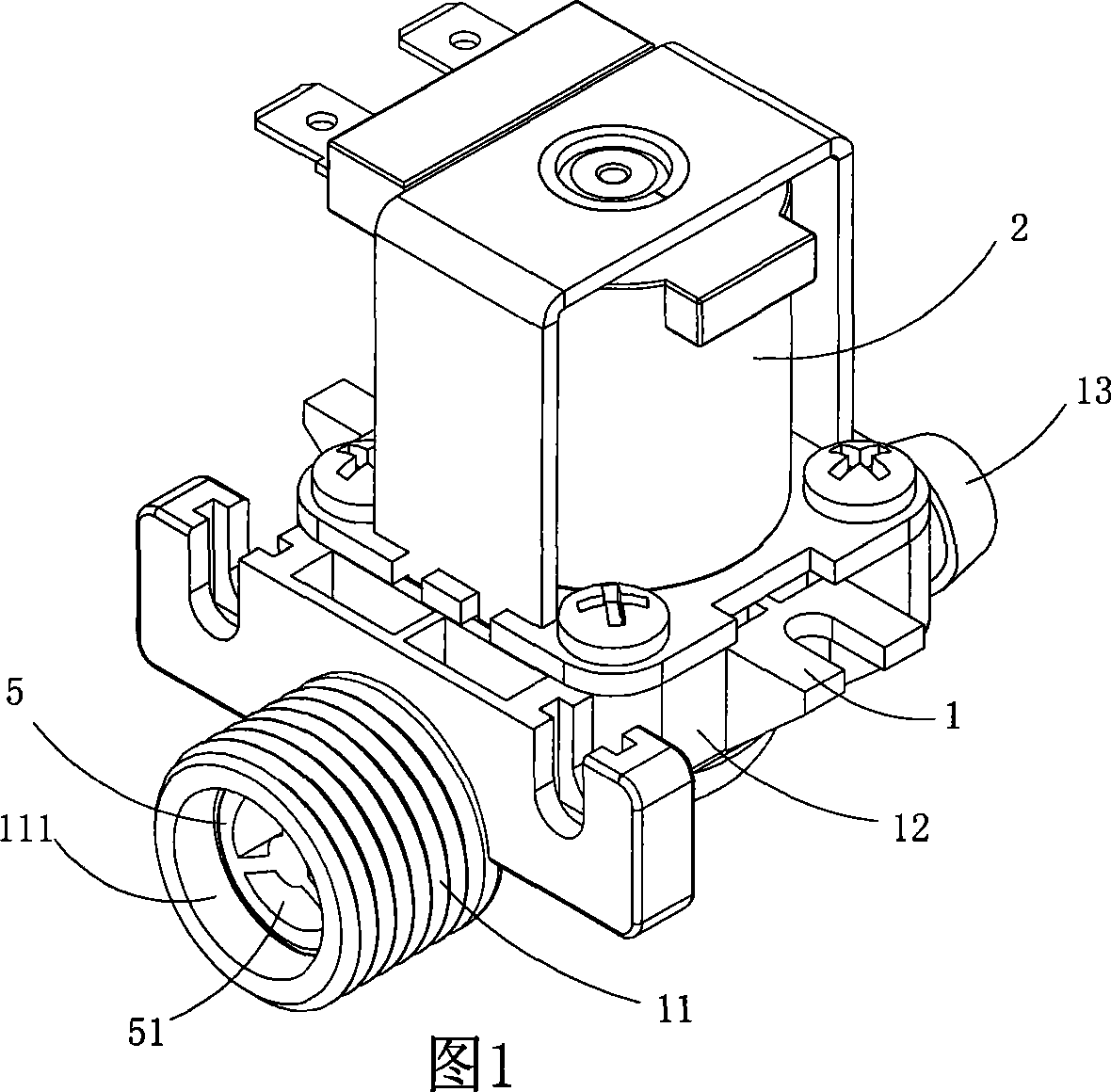
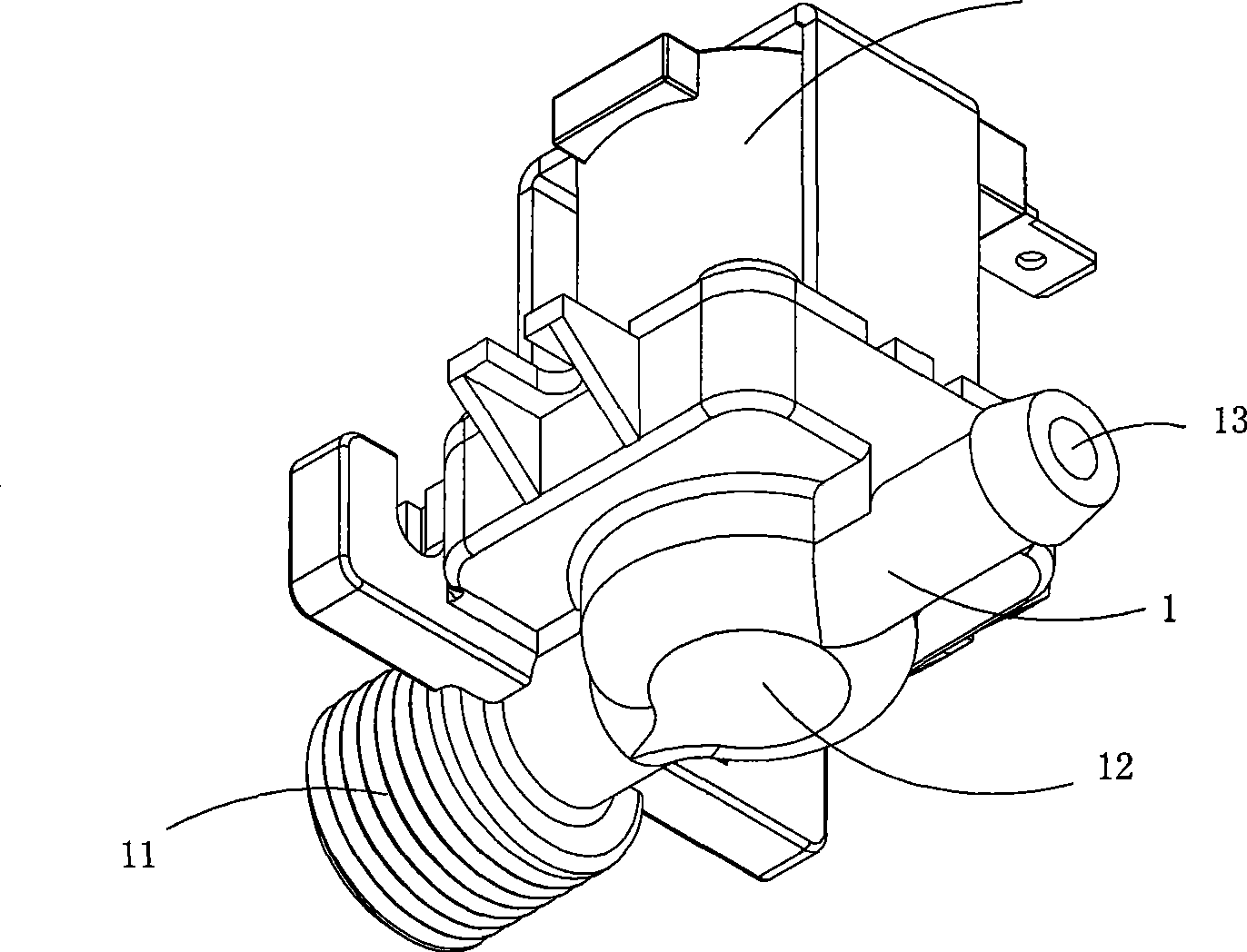
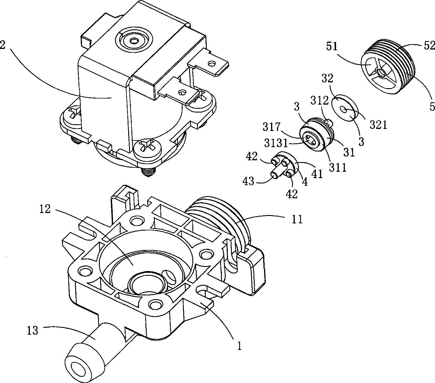
[0049] Figures 1 to 16 show the first specific embodiment of the present invention, wherein Figure 1 is a schematic perspective view of the first structure of the invention; figure 2 It is a three-dimensional structural diagram of the one-way constant flow check valve shown in Figure 1 viewed from another angle; image 3 It is a schematic diagram of an exploded structure of the one-way constant-current check valve shown in FIG. 1; FIG. 4 is a schematic diagram of an exploded structure of the one-way constant-current check valve shown in FIG. 1 viewed from another angle; Figure 5 It is a three-dimensional structural diagram of the one-way constant current check valve shown in Figure 1 after the electromagnetic on-off device is removed; Figure 6 yes Figure 5 The schematic diagram of the half-section structure of the one-way constant-current check valve after the electromagnetic on-off device is removed; Fig. 7 is a three-dimensional structure of the positioning element of th...

Embodiment 2

[0059] Figure 17 and Figure 18 A second embodiment of the invention is shown in which, Figure 17 It is a schematic diagram of a three-dimensional structure of the deflector in the second structure of the present invention; Figure 18 yes Figure 17 The three-dimensional structure schematic diagram of the deflector shown when viewed from another angle.

[0060] This embodiment is basically the same as Embodiment 1, the difference is: see Figure 17 and Figure 18 The main body 311 of the deflector is provided with two to six pillars 314 protruding axially for supporting the flow restrictor 32 at its liquid inlet end, and the gaps between adjacent pillars 314 form a liquid inlet channel, The liquid inlet channel communicates with the liquid outlet channel 313 in the deflector body 311 . At the liquid inlet end, there is no longer a radially concave liquid inlet groove 315 . This embodiment only relies on the deformation of the flow restrictor 32 in different degrees un...

Embodiment 3

[0062] Figure 19 and Figure 20 A third embodiment of the invention is shown in which, Figure 19 It is a three-dimensional structural schematic diagram of the deflector in the third structure of the present invention; Figure 20 yes Figure 19 The three-dimensional structure schematic diagram of the deflector shown when viewed from another angle.

[0063] This embodiment is basically the same as Embodiment 1, the difference is: see Figure 19 and Figure 20 , the deflector main body 311 is radially provided with two to six concave liquid inlet grooves 315 at its liquid inlet end, and the liquid inlet grooves 315 and the liquid outlet channels in the deflector main body 311 313 connected. At the liquid inlet end, there is no longer a pillar 314 protruding in the axial direction for supporting the restrictor 32 . This embodiment only relies on the deformation of the flow restrictor 32 in different degrees under different water pressures, and adjusts the gap size of each l...


PUM


Abstract

The invention discloses a unidirectional constant-current check valve, comprising a valve body and an electromagnetic on-off component which is used for turning on and turning off the liquid pipe in the valve body; the valve body comprises a liquid inlet passage, a connection pipe which is used for arranging the electromagnetic on-off component, and a liquid outlet pipeline; a constant current device and a check device are sequentially arranged in the liquid inlet passage in the liquid passage direction; the constant-current device is fixedly arranged in the liquid inlet pipeline and is provided with a liquid outlet; the check device can reciprocate to move in the liquid inlet pipeline under the driving of the liquid flow; when the check device moves approaching to the constant current device with the liquid flowing, the liquid outlet of the constant current device is finally jammed, thus preventing the circumfluence of the liquid. The unidirectional constant-current check valve has the functions of automatically adjusting the liquid inlet quantity and obtaining stable liquid outlet quantity (namely realizing the constant flowing function), and has the advantages of preventing the circumfluence of the liquid.

Description

technical field [0001] The invention belongs to the technical field of valve body structure design, and in particular relates to a one-way constant flow check valve used in liquid pipelines. Background technique [0002] The traditional cleaning work after going to the bathroom is to wipe with paper towels. The disadvantage is that there are a small amount of irritating chemicals in the paper itself, and it may also carry a large number of bacteria and viruses. Long-term use, Not only is hygiene difficult to guarantee, but it can also easily lead to sensitive skin damage and hidden dangers of disease. [0003] The current popular method is to wash the buttocks with hot water, and then dry them with warm air. While ensuring cleanliness and sanitation, it can massage and protect the buttocks, making people feel refreshed after use. It can also prevent and treat hemorrhoids, constipation and various diseases. effect. [0004] In order to make users feel comfortable, the flush...

Claims


Application Information

Patent Timeline
Patent Type & Authority Applications(China)
IPC IPC(8): F16K17/34F16K15/00F16K31/06F16K27/00
Inventor 陈登满吴方忠
Owner 吴方忠
Why Eureka
Try Eureka