
Digital oscilloscope and method for controlling display waveform

A technology of digital oscilloscope and waveform display, which is applied in the direction of digital variable display, etc., which can solve the problems of inconvenient operation and achieve the effects of small space occupation, reduced operating range, and less error-prone

Inactive Publication Date: 2010-09-01
THE 41ST INST OF CHINA ELECTRONICS TECH GRP
View PDF2 Cites 1 Cited by
  • Summary
  • Abstract
  • Description
  • Claims
  • Application Information

AI Technical Summary

Problems solved by technology

[0005] One of the purposes of the present invention is to provide an oscilloscope that facilitates manipulation of the displayed waveform in order to overcome the disadvantages of inconvenient operation in the prior art; the second purpose of the present invention is to provide a method for manipulating the displayed waveform

Method used


Image

  • Digital oscilloscope and method for controlling display waveform
  • Digital oscilloscope and method for controlling display waveform
  • Digital oscilloscope and method for controlling display waveform

Examples


Embodiment Construction

[0019] One, the composition of the digital oscilloscope provided by the present invention:

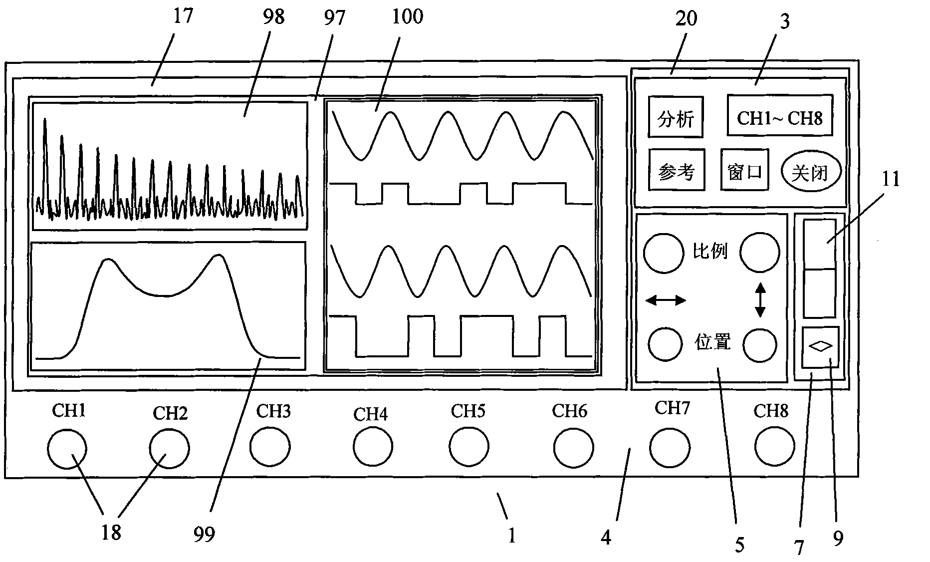
[0020] like figure 1 As shown, the present invention provides a front elevation view of a microprocessor-based digital oscilloscope 1, the signal input connector 18 is installed at the lower end of the front panel 4, and the display screen 17 is installed on the left side of the front panel 4, and the display screen 17 The right side is the operation keyboard 20, and here only shows three main operating areas for illustrating the present invention: waveform setting area 3, waveform display adjustment knob area 5, waveform selection area 7, waveform setting area 3 includes 4 commonly used waveforms / The function keys of the setting menu of the waveform window and a key to quickly close the "current waveform". For example, the operation of the keys "CH1~CH8" can pop up the "channel setting" menu to set the waveform switch, impedance, coupling and probe of the 8 channels coefficients and...


PUM


Abstract

The invention relates to a microprocessor or computer-based digital oscilloscope and a method for manipulating and displaying waveforms in the digital oscilloscope, the digital oscilloscope and the method are characterized in that the digital oscilloscope is provided with a bar-shaped touch device (11) for waveform selection, the coordinates of two key points on the top and the bottom part of each displayed waveform on a display screen are taken as fixation points, a touch point in the bar-shaped touch device (11) is mapped in the display screen by the linear corresponding relation to obtain a mapping position along the vertical direction, and the waveform represented by the fixation points which are most close to the mapping position is selected as the current waveform. When in waveform section, the digital oscilloscope has the advantages of faster, more intuitive and more difficult in making mistakes; the method does not need the precise positioning, the waveform selection device occupies smaller space, thereby being capable of reducing the operation range and reducing the hand fatigue; the placement of the waveform selection device is more flexible, and the waveform selection device can be moved relative to the waveform display screen.

Description

technical field [0001] The present invention relates to a digital oscilloscope based on a microprocessor or a computer, and a method for manipulating a displayed waveform in the digital oscilloscope. Background technique [0002] An oscilloscope is capable of displaying several waveforms simultaneously, each depicting the magnitude of a different signal versus time. This oscilloscope allows the operator to adjust various display parameters of each displayed waveform, such as the vertical position of the waveform on the oscilloscope screen, vertical display scale, horizontal observation position, horizontal display scale, trigger level, color, brightness, etc. [0003] When the number of displayed waveforms is small, some oscilloscopes (such as the popular 2-channel or 4-channel oscilloscopes) provide a set of commonly used display parameters for controlling each waveform (usually the vertical position and vertical display ratio of the waveform on the oscilloscope screen). S...

Claims


Application Information

Patent Timeline
Patent Type & Authority Patents(China)
IPC IPC(8): G01R13/02
Inventor 戚瑞民布乃洪张永坡粟永强
Owner THE 41ST INST OF CHINA ELECTRONICS TECH GRP
Learn More