
Signal receiving and transmitting device of digital magnetic nuclear resonance lock

A transceiver device, nuclear magnetic resonance technology, applied in the direction of magnetic resonance measurement, etc., can solve the problems of complex digital lock receiver structure, demodulation phase artifacts, gain imbalance, etc., to improve versatility and flexibility, simplify design and structure, performance-enhancing effects

Active Publication Date: 2009-04-22
ウーハン ジョンケ ニウジン マグネティック レゾナンス テクノロジー カンパニー リミテッド
View PDF0 Cites 22 Cited by
  • Summary
  • Abstract
  • Description
  • Claims
  • Application Information

AI Technical Summary

Problems solved by technology

Both traditional analog and digital locks use multi-stage mixing to output a lock signal with a fixed frequency, and the analog quadrature detection technology is used in the lock receiver. When performing phase-sensitive detection, the gain imbalance or phase of the two channels errors, are likely to cause demodulation phase artifacts
At present, the newer lock system uses digital technology in the lock receiver to overcome some shortcomings of the traditional analog lock receiver; however, although this traditional digital lock receiver uses a high-speed analog-to-digital conversion chip (ADC) Signal processing chip (DSP), but it still uses analog quadrature detection, and the structure of the digital lock receiver in this mode is relatively complicated and the cost is relatively high

Method used


Image

  • Signal receiving and transmitting device of digital magnetic nuclear resonance lock
  • Signal receiving and transmitting device of digital magnetic nuclear resonance lock

Examples


Embodiment Construction

[0031] Below in conjunction with accompanying drawing, the present invention is described in further detail:

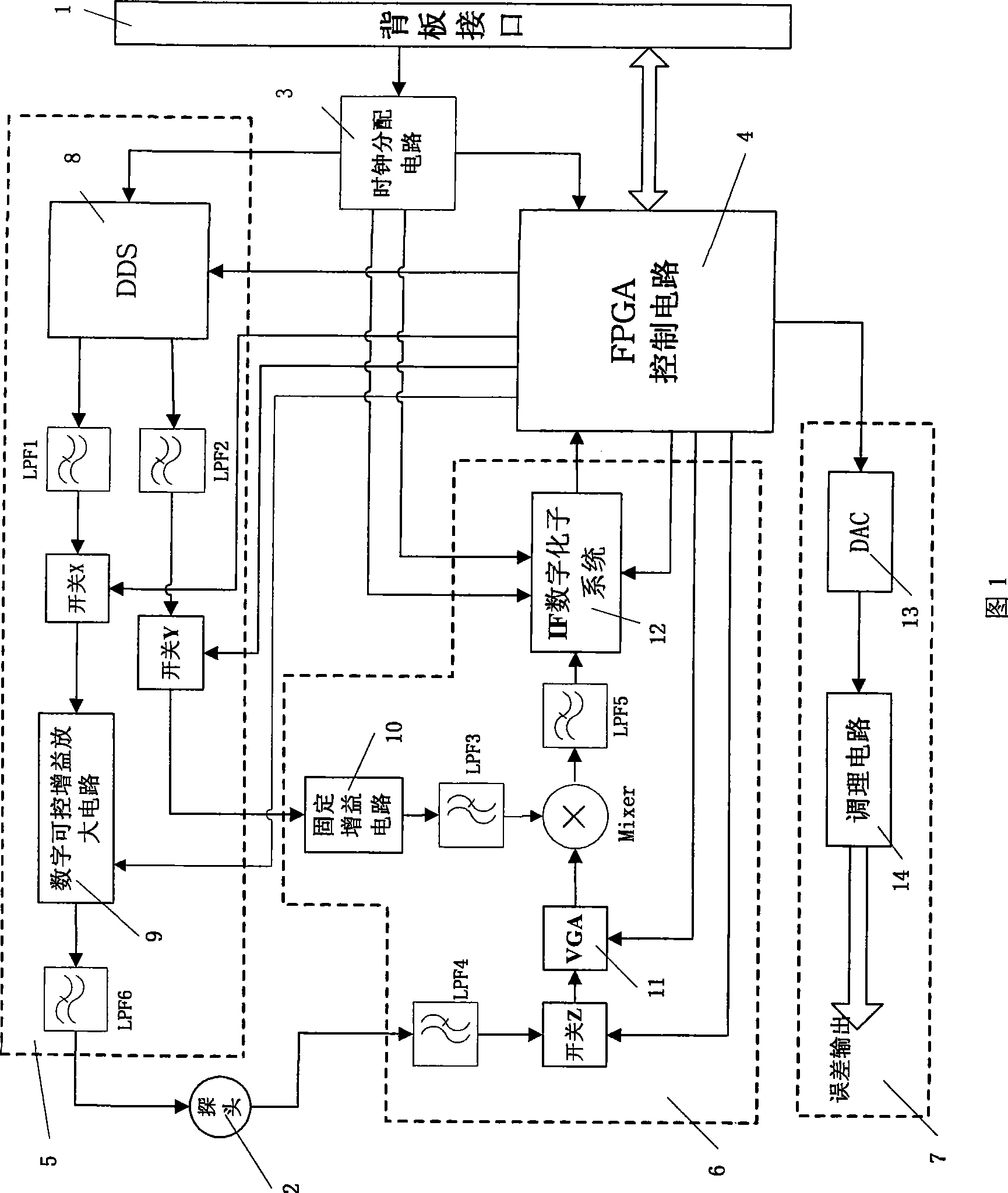
[0032]According to FIG. 1 , it can be known that the lock signal transceiving device is mainly composed of three parts: a lock transmitter 5 , a lock receiver 6 and a lock error output unit 7 . The FPGA control circuit 4, as the control core, is connected to the clock distribution circuit 3 and the backplane interface 1 respectively, and is used to receive external clock signals and control commands from the backplane interface 1, and mainly complete the control of each module circuit and the sending and receiving of lock information , and PID control and other work. Wherein clock distribution circuit 3 receives 240MHz signal input to comparator ADCMP553 (ADI company) by backplane interface 1, then is connected to clock distribution chip AD9514 (ADI company), the clock that clock distribution chip AD9514 outputs is used for FPGA control circuit 4, Model EP2C8Q208, di...


PUM


Abstract

The invention discloses a digital nuclear magnetic resonance lock signal transmitter receiver set which consists of a lock transmitter, a lock receiver and a lock error output unit. The transmitter receiver set is characterized in that: an FPGA control circuit is connected with a clock distribution circuit and a backboard interface, a digital frequency synthesizer is respectively connected with the clock distribution circuit, a low pass filter and the FPGA control circuit; a digital variable gain amplification circuit is connected with the low pass filter and the FPGA control circuit respectively; the low pass filter is connected with the digital variable gain amplification circuit and a probe respectively; the low pass filter is connected with the probe and a switch respectively; the variable gain amplification circuit is connected with the FPGA control circuit; a frequency mixer is connected with the low pass filter and the variable gain amplification circuit respectively, an IF digital sub-system is connected with the clock distribution circuit, the FPGA control circuit and the low pass filter respectively; and a digital-to-analog converter (DAC) is connected with the FPGA control circuit and a conditioning circuit. The digital nuclear magnetic resonance lock signal transmitter receiver set has the advantages of digital control, good versatility and low cost, and enhance magnetic field stability and anti-interference capability.

Description

technical field [0001] The invention relates to a nuclear magnetic resonance measuring device, more specifically to a digital nuclear magnetic resonance signal transceiver, which can be used for nuclear magnetic resonance spectrometers and magnetic resonance imagers. Background technique [0002] NMR experiments require a very good stability of the magnetic field. The main purpose of the NMR spectrometer lock transceiver and lock compensation system is to stabilize the static magnetic field, which is an essential part of the NMR instrument. In order to solve the drift of the static magnetic field, the "field-frequency interlocking" method is usually used to lock the static magnetic field. There are two main types of technical realization of field-frequency interlocking: one is analog lock, which directly amplifies and filters the dispersion signal by analog circuit and then adds it to the magnetic field compensation coil; the other is digital lock, which uses digital contro...

Claims


Application Information

Patent Timeline
IPC IPC(8): G01R33/36
Inventor 刘朝阳姜婷婷毛文平裘鉴卿叶朝辉
Owner ウーハン ジョンケ ニウジン マグネティック レゾナンス テクノロジー カンパニー リミテッド
Learn More