
Audio and video wireless transmitting device

A wireless transmitting device, audio and video technology, applied in the direction of TV, color TV, color TV parts, etc., can solve the problems of narrow bandwidth, complex structure, huge shape, etc., and achieve the goal of undistorted sound, clear image and improved quality Effect

Inactive Publication Date: 2006-06-21
邓明友
View PDF0 Cites 0 Cited by
  • Summary
  • Abstract
  • Description
  • Claims
  • Application Information

AI Technical Summary

Problems solved by technology

[0002] In the prior art, there are many switching devices for video signals and radio frequency signals, but few transmitting devices, which can be basically divided into two types. One is a transmitting device similar to a TV station, which has a large shape and a complex structure. One is a transmitting device similar to mobile phones and paging. The transmitting device is a single-frequency point transmission with a narrow bandwidth.

Method used


Image

  • Audio and video wireless transmitting device
  • Audio and video wireless transmitting device
  • Audio and video wireless transmitting device

Examples


Embodiment Construction

[0020] The present invention will be further elaborated below according to the drawings and specific embodiments.

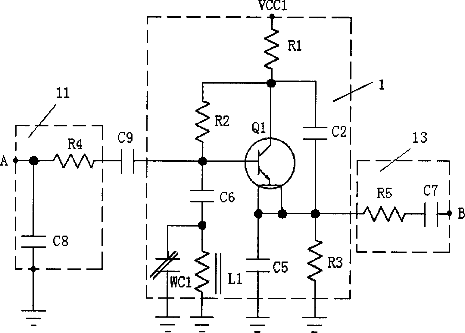
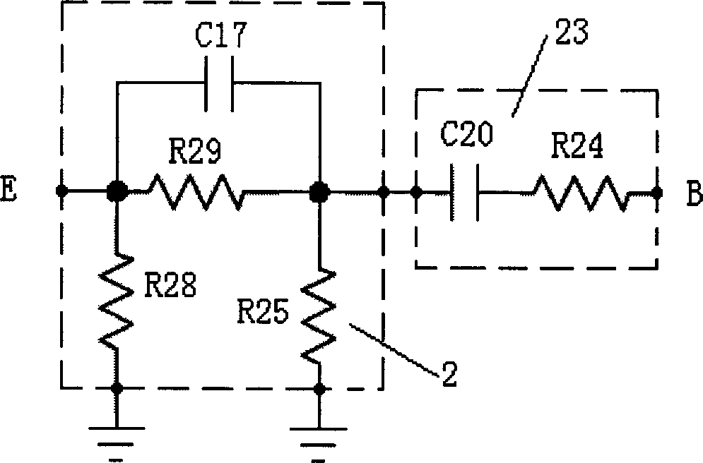
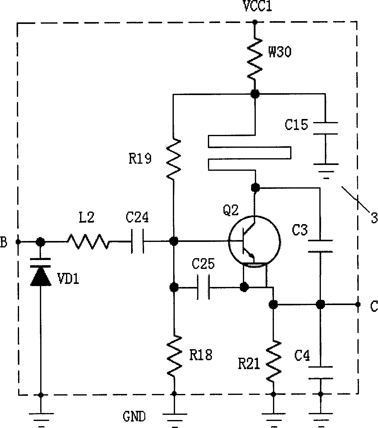
[0021] An audio and video wireless transmitter includes an audio primary modulation circuit 1 , a video pre-emphasis circuit 2 , a voltage-controlled oscillation circuit 3 and an amplification circuit 4 .

[0022] like figure 1 As shown, the circuit at the audio input end includes a filter circuit 11 , an audio primary modulation circuit 1 and an isolation coupling circuit 13 in sequence. The filter circuit 11 is a resistance-capacitance filter circuit composed of the fourth resistor R4 and the eighth capacitor C8: one end of the fourth resistor R4 is connected to the audio input terminal A and one end of the eighth capacitor C8, and the other end is connected to the primary audio modulation circuit 1 The input ends are connected; the other end of the eighth capacitor C8 is grounded.

[0023] The audio primary modulation circuit 1 is mainly a capacitive three-p...


PUM


Abstract

The invention relates to a wireless emission device with audio / video transmission function and emission frequency point controlled by phase-locking loop and SCM, which comprises an audio primary modulation circuit, a video preemphasis circuit, a voltage-controlled oscillatory circuit contained a varactor diode with anode grounding and cathode as input end of the circuit to electrical connect with output ends of audio primary modulation circuit and video preemphasis circuit and with bases of the second triode by the second inductance and the 24th capacitor, a second triode with collector electrical connected to power and emitter ac output end of the circuit connected to the amplification circuit, and a third capacitor crossed between the collector and emitter of the second triode; a amplification circuit, and a phase-locking loop circuit with a phase-locking loop chip, a SCM, a switch signal circuit, a crystal oscillation and loop filter. This invention is simple and high reliable with 8MHZ bandwidth, and can be used to monitor in wide range.

Description

[technical field] [0001] The invention relates to a wireless transmitting device, in particular to a wireless transmitting device with audio and video transmission functions. [Background technique] [0002] In the prior art, there are many switching devices for video signals and radio frequency signals, but few transmitting devices, which can be basically divided into two types. One is a transmitting device similar to a TV station, which has a large shape and a complex structure. One is a transmitting device similar to a mobile phone or a paging device. The transmitting device is a single-frequency point transmission with a narrow bandwidth. [Content of the invention] [0003] The purpose of the present invention is to solve the wireless radio frequency transmission of video and audio signals. [0004] The technical solution adopted by the present invention to solve the technical problem is: an audio and video wireless transmitting device, including an audio primary modul...

Claims


Application Information

Patent Timeline
Patent Type & Authority Applications(China)
IPC IPC(8): H04N5/38
Inventor 邓明友
Owner 邓明友
Learn More