
Temperature compensation rod and method for manufacturing multiplexing and de-multiplexing non-heat array wave guide grating

A technology of temperature compensation and waveguide grating, which is applied in the direction of wavelength division multiplexing system and optical waveguide coupling, can solve the problems of high device cost, inability to realize multiplexing and demultiplexing functions at the same time, large size, etc., and achieve good repeatability , low cost, small size effect

Active Publication Date: 2009-04-22
GUANGXUN SCI & TECH WUHAN
View PDF0 Cites 6 Cited by
  • Summary
  • Abstract
  • Description
  • Claims
  • Application Information

AI Technical Summary

Problems solved by technology

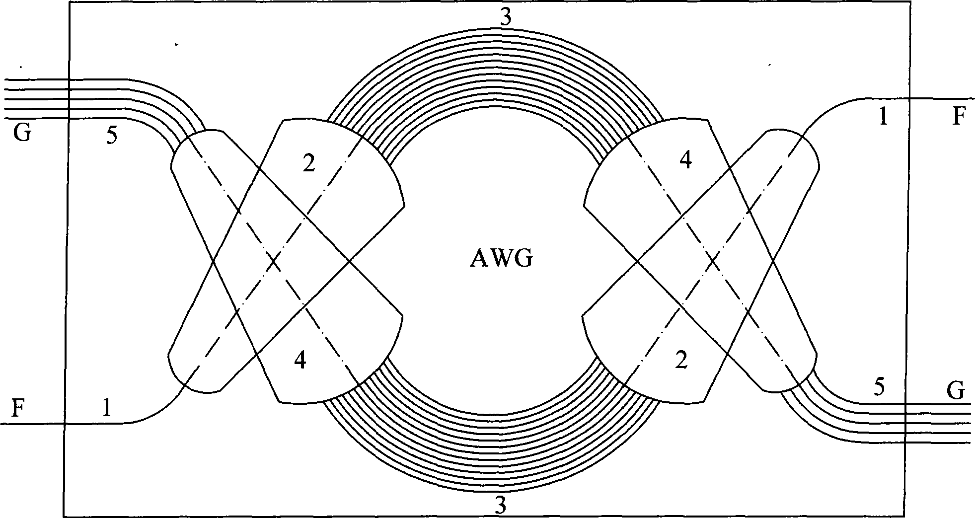
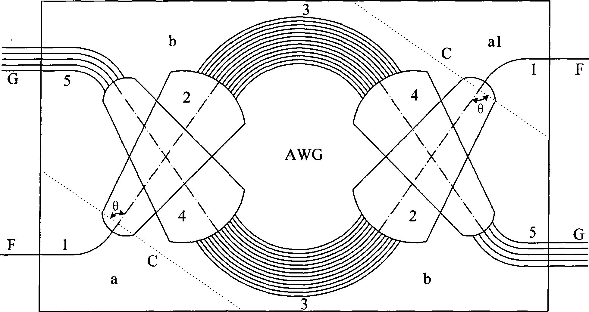
[0003] In order to improve the efficiency of chip research and development and reduce the cost of chip development, such as figure 1 As shown, one chip contains two AWGs, but due to the difference in material growth and waveguide manufacturing process errors, the operating temperature points of the two AWGs are different. Therefore, the AWG module with a temperature control circuit can only use these two AWGs. One of the AWG; in addition, because an AWG module can only realize the multiplexing function or the demultiplexing function, and cannot realize the multiplexing and demultiplexing functions at the same time, it is currently used in VMUX, OADM (ROADM) and OXC In other devices, two identical AWG modules need to be used, one for multiplexing and the other for demultiplexing, which leads to the disadvantages of high cost and large size of the device

Method used


Image

  • Temperature compensation rod and method for manufacturing multiplexing and de-multiplexing non-heat array wave guide grating
  • Temperature compensation rod and method for manufacturing multiplexing and de-multiplexing non-heat array wave guide grating
  • Temperature compensation rod and method for manufacturing multiplexing and de-multiplexing non-heat array wave guide grating

Examples


Embodiment Construction

[0033] The temperature compensating rod and the method for manufacturing multiplexing and demultiplexing athermal arrayed waveguide gratings of the present invention will be described in detail below with reference to the drawings of the embodiments.

[0034] Such as Figure 7 , Figure 8 As shown, the temperature compensation rod of the present invention includes a rod body 8 and "I"-shaped structures 7 respectively formed at both ends of the rod body 8, wherein the upper end structure 7.2. There is a gap between 1 and the rod body 8, and the lower end structure 7.2.2 is integrally formed with the rod body 8; the upper structure 7.1.1 of the "I"-shaped structure 7 on the other side of the rod body 8 is integrated with the rod body Formed, and a gap is formed between the lower end structure 7.1.2 and the rod body 8. The middle parts 7.1 and 7.2 of the "I" shape have the characteristics of thin, long and high in size, so that they can produce elastic deformation in the thickn...


PUM


Abstract

The invention discloses a temperature compensation rod and a method for making an athermal array waveguide grating (AWG) for multiplexing and demultiplexing. The temperature compensation rod consists of a rod body and two I-shaped structures respectively formed on two ends of the rod body, clearance is formed between the upper end structure of the I-shaped structure at one side of the rod body and the rod body while the lower end structure of the I-shaped structure is integrated with the rod body into a whole; the upper end structure of the I-shaped structure at the other side of the rod body is integrated with the rod body into a whole while clearance is formed between the lower end structure of the I-shaped structure and the rod body. The method comprises the following steps: coupling two AWGs on a chip; cutting the chip into three parts along cut lines; fixing a third part and respectively arranging a first part and a second part on a 6D precision fine turning frame so as to realize coupling alignment and restore the parts to the original shapes for online testing; carrying out the online testing after arranging the temperature compensation rod; and curing two temperature compensation rods on positions at which the two rods are arranged on the three parts of the chip if the three parts are tested qualified. The temperature compensation rod has the advantages of lower cost, large batch, good repeatability, smaller size, good stability and extremely simple process.

Description

technical field [0001] The invention relates to a temperature-insensitive arrayed waveguide grating. In particular, it relates to a temperature compensation rod and a temperature compensation rod used in optical communication WDM systems to realize multiplexing or (and) demultiplexing functions, especially for devices or subsystems with both multiplexing modules and demultiplexing modules. Athermal arrayed waveguide grating method for fabricating multiplexing and demultiplexing. Background technique [0002] Ordinary AWG (Arrayed Waveguide Grating) is made of silicon-based silicon dioxide technology. The refractive index of silicon dioxide changes with temperature, and the size of the waveguide also changes with temperature, resulting in the AWG's various channels. The wavelength changes with the temperature. Usually, the temperature change of the central wavelength of this type of device is 0.011nm / ℃, but the communication system requires the wavelength of the optical sign...

Claims


Application Information

Patent Timeline
Patent Type & Authority Applications(China)
IPC IPC(8): G02B6/34H04J14/02
Inventor 周天宏马卫东
Owner GUANGXUN SCI & TECH WUHAN
Learn More