Radiating device

A technology for a heat sink and a heat sink, which is applied in cooling/ventilation/heating transformation, instruments, electrical digital data processing, etc. Heat dissipation efficiency, simple manufacturing process, and the effect of increasing the heat dissipation area

Inactive Publication Date: 2009-04-22
FU ZHUN PRECISION IND SHENZHEN +1
View PDF0 Cites 9 Cited by
  • Summary
  • Abstract
  • Description
  • Claims
  • Application Information

AI Technical Summary

Problems solved by technology

However, since the finned heat sink needs to be fixedly connected by welding or other means, and through holes must be opened on the heat sink to connect the heat pipes, the manufacturing process is relatively complicated, and the manufacturing cost of the heat sink is increased.
In addition, the simple one-way heat transfer of the heat pipe also limits the heat dissipation efficiency of the heat sink.

Method used


Image

  • Radiating device
  • Radiating device
  • Radiating device

Examples


Embodiment Construction

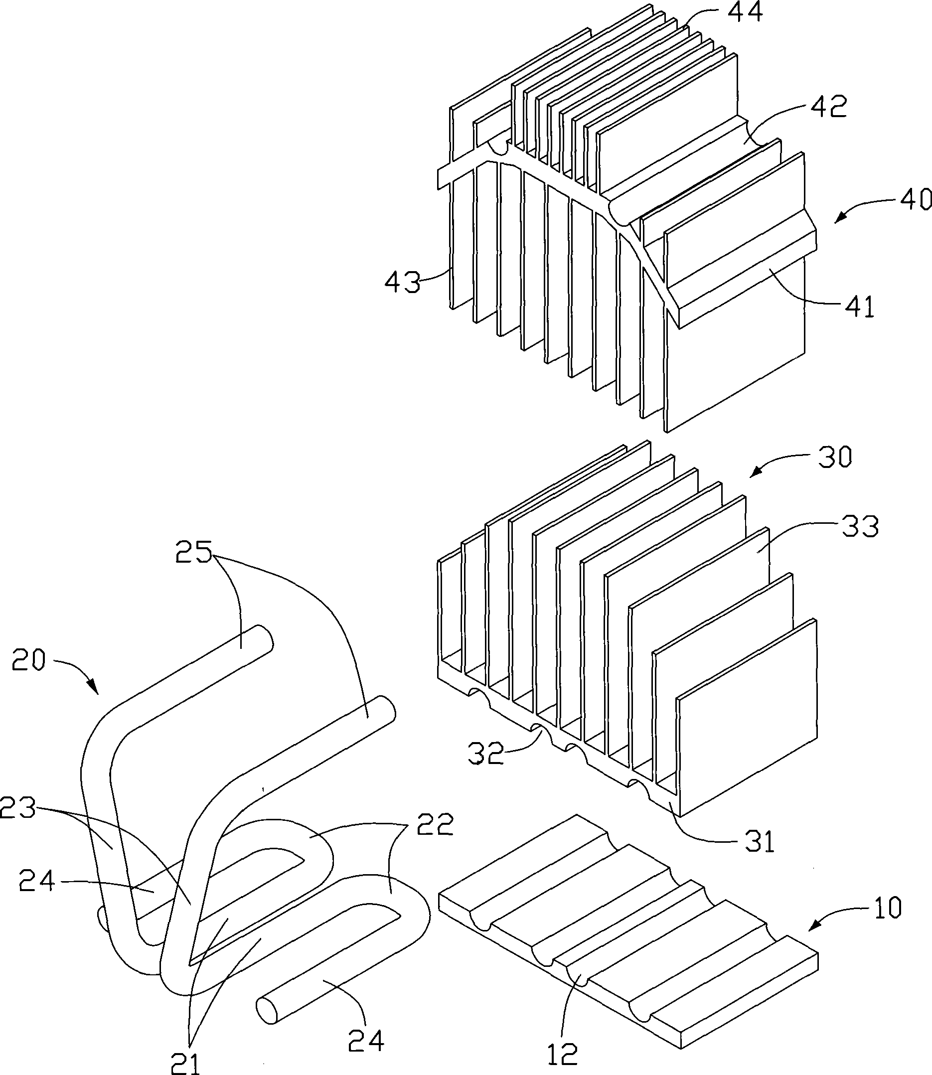
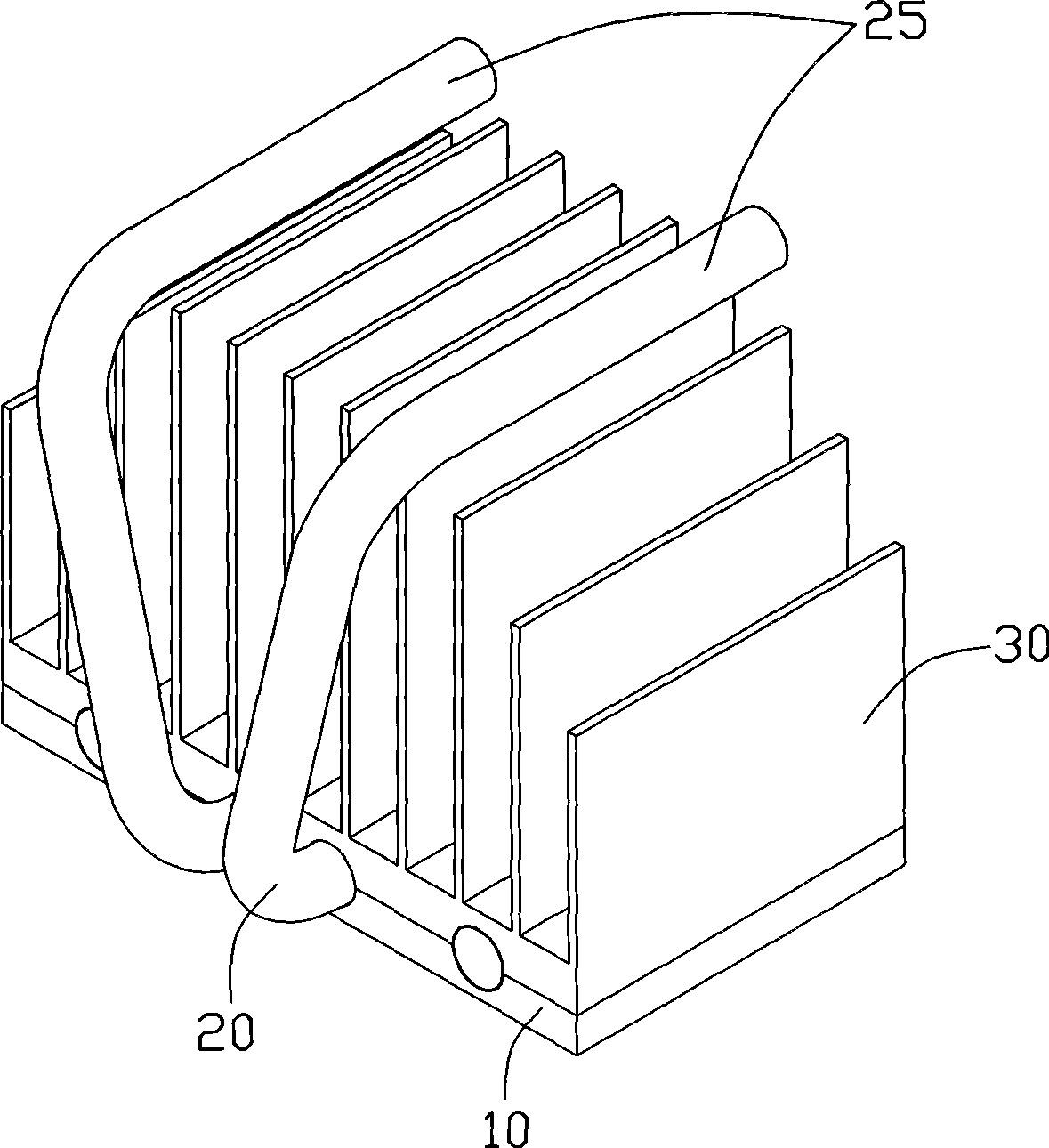
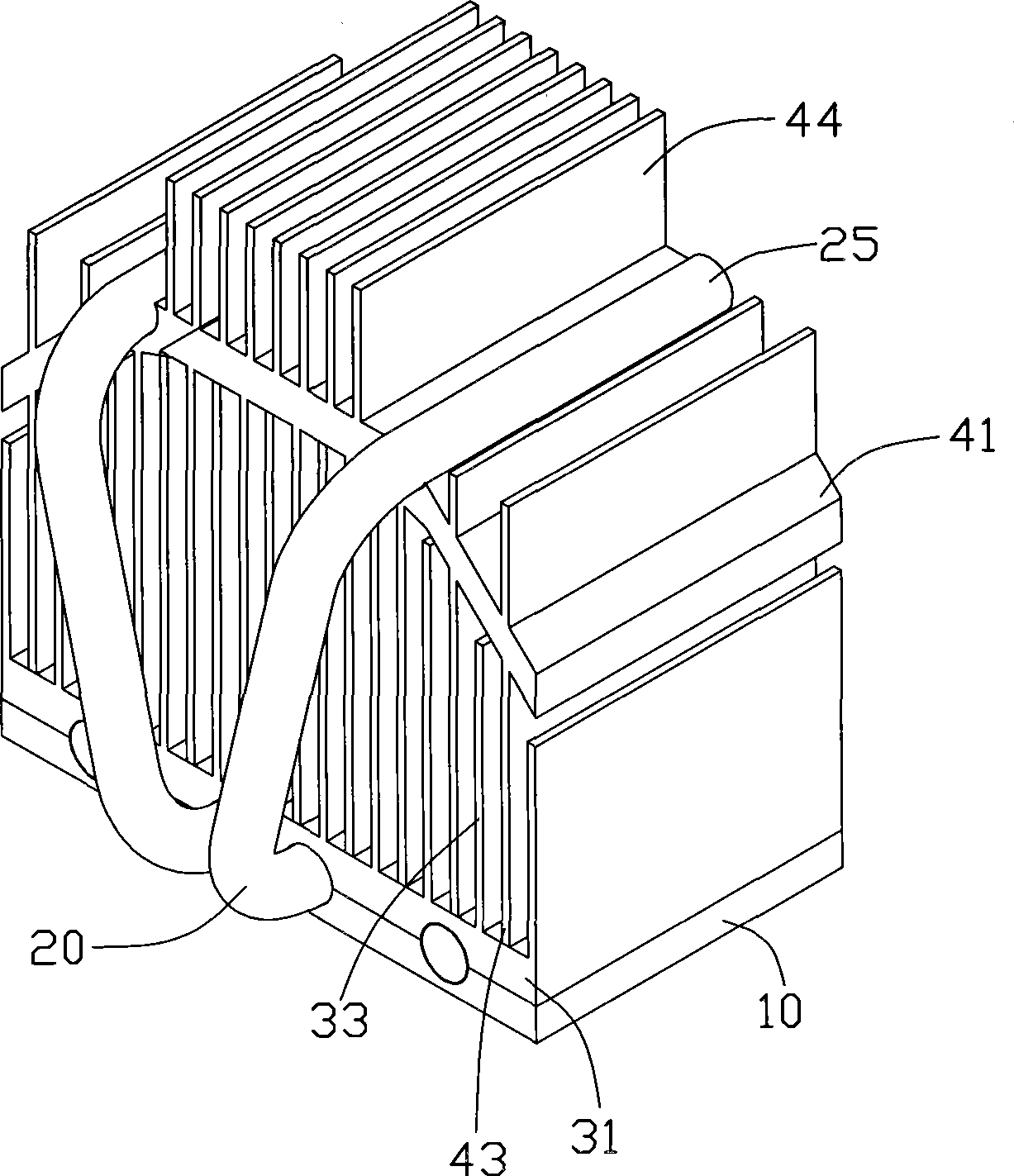
[0012] figure 1 A preferred embodiment of the heat sink of the present invention is shown. The cooling device includes a base 10, a first heat sink 30 placed on the base 10, a second heat sink 40 placed on the first heat sink 30 and a connection base 10, the first heat sink 30 and the second heat sink 30. Two heat pipes 20 of the second radiator 40 . The cooling device is mounted on a circuit board (not shown) for dissipating heat from a heat-generating electronic component (not shown), such as a CPU.

[0013] The base 10 is made of a material with high thermal conductivity, such as copper or aluminum. The base 10 is in the shape of a rectangular block, the bottom of which is used to contact the heating electronic components, thereby absorbing the heat emitted by the heating electronic components. Four semicircular grooves 12 parallel to each other are formed on the top surface of the base 10 . Wherein the two grooves 12 in the middle of the top surface of the base 10 are ...


PUM


Abstract

The invention relates to a radiating device used for radiating an electronic element, comprising a base contacting with the electronic element, a first radiator arranged on the base, a second radiator arranged on the first radiator and at least one heat tube connecting the base with the first and the second radiators. The first radiator comprises a base plate and a plurality of radiating fins extending from the base plate. The second radiator comprises a base plate and a plurality of radiating fins extending from the base plate. The at least one heat tube comprises a vaporizing section and a first and a second condensing sections parallel to the vaporizing section. The vaporizing section and the first condensing section are arranged between the base and the base plate of the first radiator. The second condensing section is arranged on the base plate of the second radiator. The radiator of the radiating device has simple manufacturing process and relatively large radiating area. Furthermore, the heat tube of the radiating device comprises two condensing sections so that fast heat transferring and evening effect can be achieved, thereby improving the radiating efficiency of the radiating device.

Description

technical field [0001] The invention relates to a heat dissipation device, in particular to a heat dissipation device used for heat dissipation of electronic components. Background technique [0002] High-power electronic components such as computer central processing unit, north bridge chip, and graphics card will generate a lot of heat during operation. If the heat cannot be effectively dissipated, the temperature will directly rise sharply, which will seriously affect the normal operation of electronic components. . Therefore, it is necessary to add a heat sink to dissipate heat from these electronic components. [0003] Usually a heat sink includes a finned heat sink. The heat sink is made of high thermal conductivity material, and includes a base contacting the heating electronic components and several fins extending outward from the base. However, with the continuous improvement of the operating speed of today's electronic components, their calorific value is also i...

Claims


Application Information

Patent Timeline
Patent Type & Authority Applications(China)
IPC IPC(8): H05K7/20H01L23/34H01L23/367H01L23/427G06F1/20
Inventor 刘鹏
Owner FU ZHUN PRECISION IND SHENZHEN
Why Eureka
Try Eureka