Position sensor with variable direction of magnetization and method of production

A magnetization direction, motion sensor technology, applied in the direction of conversion sensor output, instruments, measuring devices, etc., can solve the problem of increasing the cost of the sensor, and achieve the effect of simple structure, beneficial durability, and cost reduction

Active Publication Date: 2009-04-22
MMT股份公司
View PDF5 Cites 16 Cited by
  • Summary
  • Abstract
  • Description
  • Claims
  • Application Information

AI Technical Summary

Problems solved by technology

However, for practical applications with operating travel ranges greater than 20 mm to 25 mm, these sensors require the use of multiple probes p

Method used


Image

  • Position sensor with variable direction of magnetization and method of production
  • Position sensor with variable direction of magnetization and method of production
  • Position sensor with variable direction of magnetization and method of production

Examples


Embodiment Construction

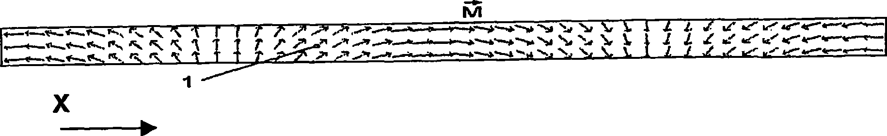
[0099] figure 1 Magnet (1) is shown with vector The magnetization represented by , the direction of this vector varies linearly along the length of the magnet in the plane defined by the direction of motion X and the direction perpendicular to the direction of motion (normal). It can be seen that the lines of force in the magnetic field inside the magnet are non-collinear, which constitutes a basic principle of the present invention.

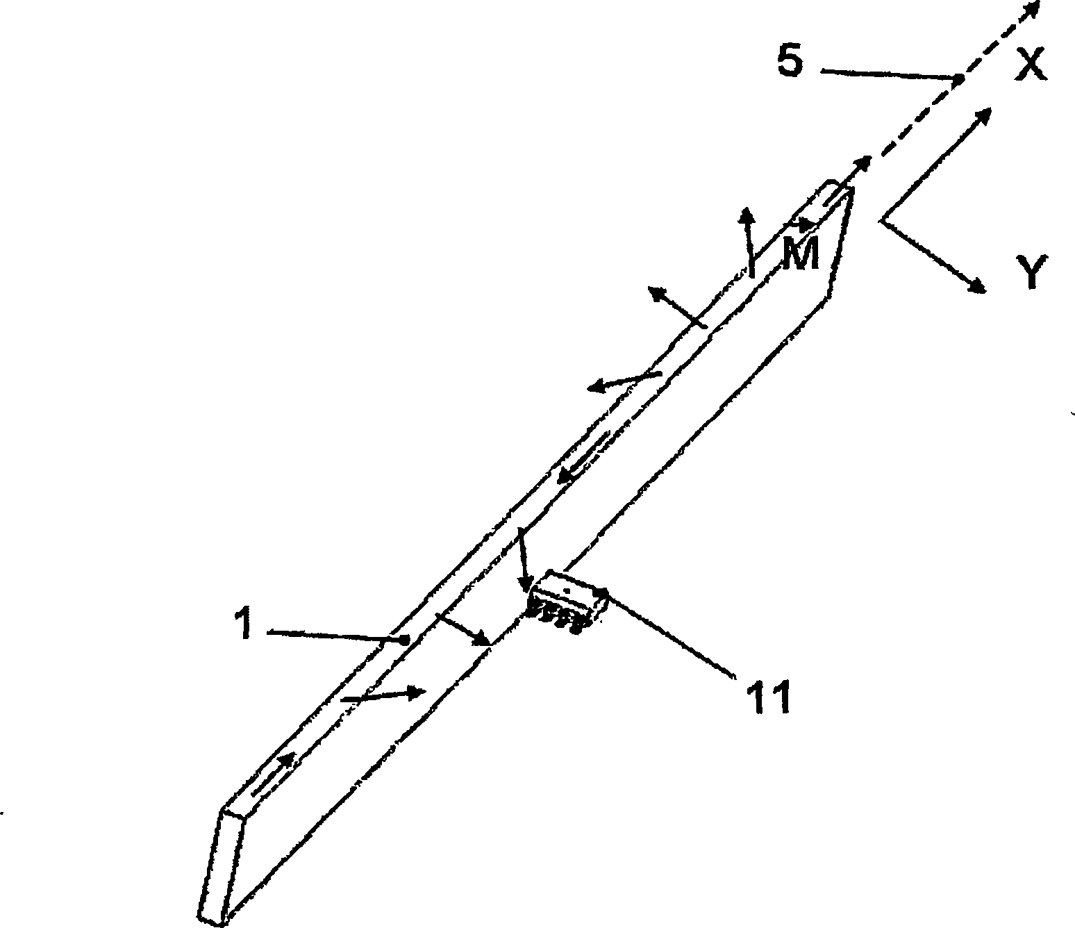
[0100] figure 2 The minimal structure of the sensor is shown: a magnet (1) moving relative to the probe (11) along a direction of motion (5) defined by axis X, axis Y being defined as normal to the surface of the magnet.

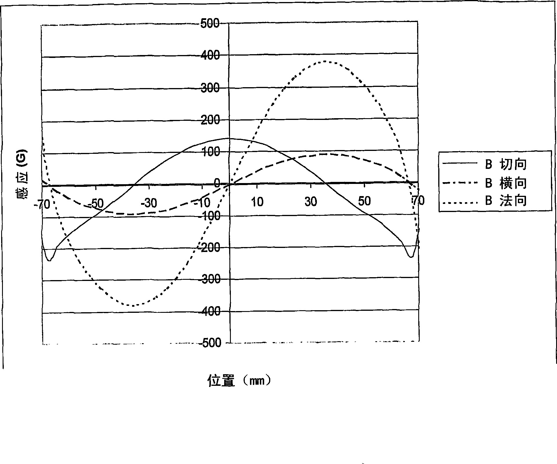
[0101] image 3 The tangential, normal and transverse components arising at a point near the magnet (1) are shown. Components Y and Z have the same phase, while the phase of component X is shifted by a quarter period.

[0102] Figure 4 The magnet (1) is shown mounted on a ferromagnetic yoke (2) that moves relative to ...


PUM


Abstract

The present invention relates to a magnetic sensor of rotary, linear or curvilinear displacement using at least one permanent magnet and at least one magnetosensitive element, which can move with respect to one another, characterized in that the magnet exhibits a direction of magnetization that varies continuously along the direction of displacement, with the exclusion of a diametral magnetization in the case of a rotary sensor.

Description

technical field [0001] The invention relates to the field of magnetic position sensors with at least one permanent magnet. [0002] The invention proposes in particular the use of permanent magnets, which have a magnetization direction that varies along the direction of motion. Background technique [0003] Sensors that detect position based on magnetic fields offer several advantages: [0004] No mechanical contact with moving parts and therefore no wear; [0005] · Not sensitive to dust; [0006] Low manufacturing costs; and [0007] ·long lasting. [0008] It is beneficial, if possible, to eliminate disadvantages present in some magnetic sensors, such as hysteresis due to ferromagnetic components as well as the remanent induction of permanent magnets (remanent induction depends on temperature variations and must in some cases be compensated, in addition , the remanence induction will be irreversibly reduced due to the aging of the magnet after a long time). [0009]...

Claims


Application Information

Patent Timeline
IPC IPC(8): G01B7/00G01B7/30
CPCG01D5/145G01B7/30G01B7/00
Inventor N·热朗斯R·阿尔洛
Owner MMT股份公司
Why Eureka
Try Eureka