Dustproof application of foam for bore hole at surface of buildings and blowing machine used thereby
A technology of building and foam, applied in the direction of drilling equipment and methods, dust removal, drilling equipment, etc., to achieve the effect of reliable connection, convenient disassembly and assembly, and simple operation
- Summary
- Abstract
- Description
- Claims
- Application Information
AI Technical Summary
Problems solved by technology
Method used
Image

Examples
Embodiment 1
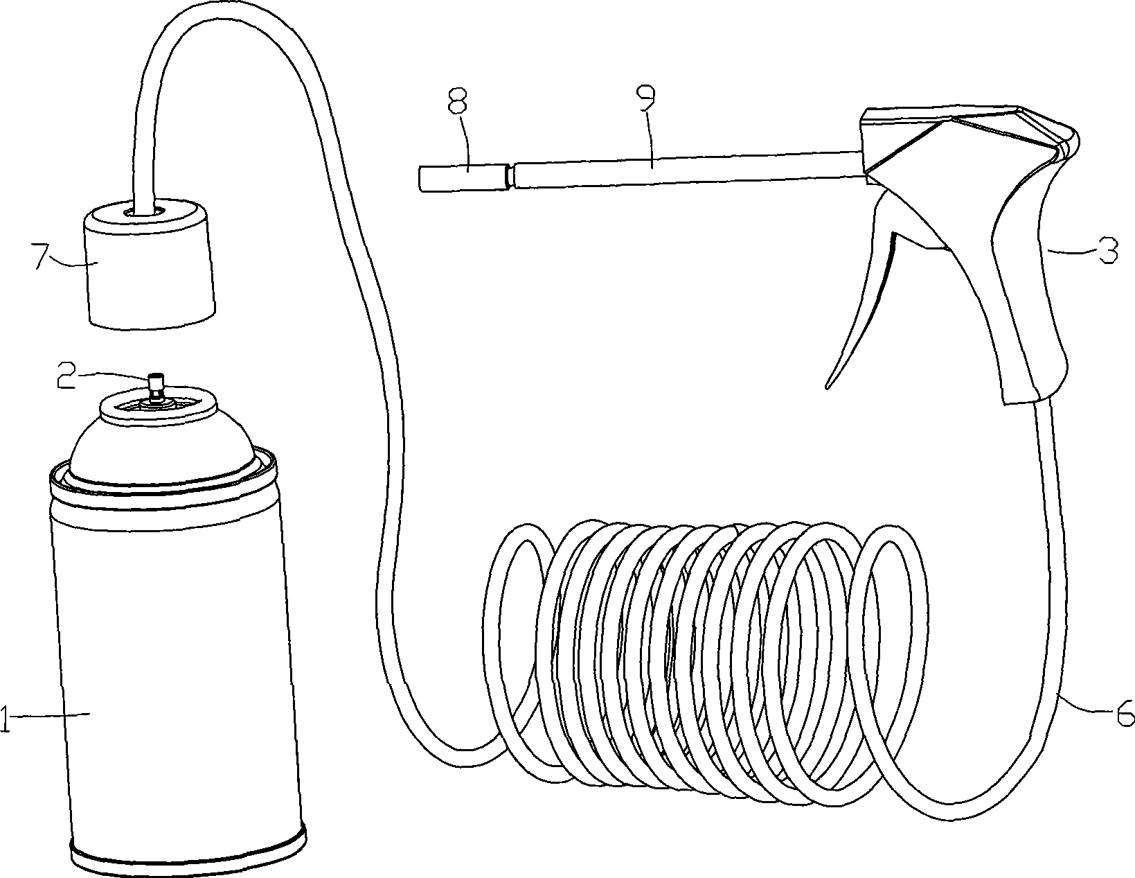
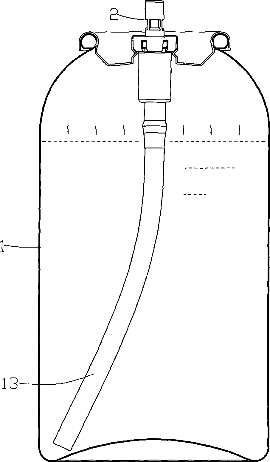
[0068] like figure 1 , figure 2 , image 3 and Figure 4 As shown, a foam aerosol injector used for dust-proof application of foam in drilling on the surface of a building is composed of an aerosol can 1 and a hand-held valve-type accelerator, wherein the aerosol can 1 is a metal integral can, The inner wall of the tank needs to be coated with anti-corrosion plastic grease. The valve 2 of the aerosol can is installed on the top of the aerosol can 1, either a male valve or a female valve. This embodiment only takes the male valve as an example. -3 and sealing ring 2-4. The valve body 2-2 is located in the aerosol can 1, the upper end of the valve body 2-2 is fixedly connected to the top of the aerosol can 1, and the lower end of the valve stem 2-1 extends into the bottom of the valve body 2-2 from top to bottom. The inner cavity is supported by the spring 2-3, and the upper end of the valve stem 2-1 protrudes from the top surface of the aerosol can 1. An inner cavity 2-1...
Embodiment 2
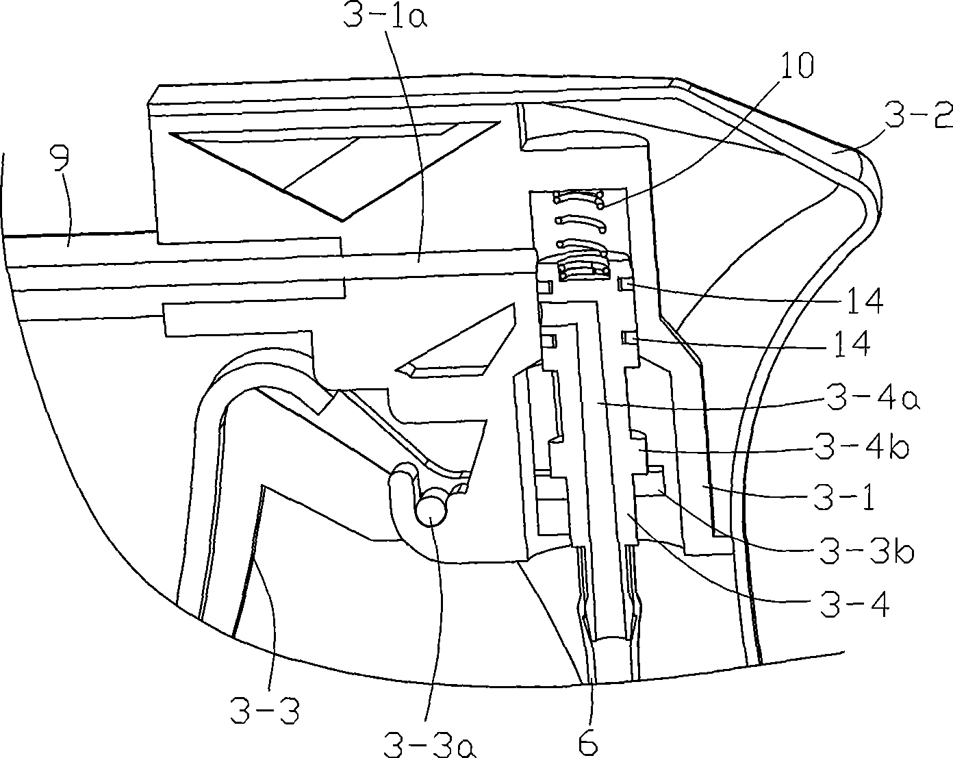
[0074] like Figure 5 , Image 6 , Figure 7 and combine image 3 , Figure 4 As shown, a foam aerosol dispenser used for dust-proof application of foam in drilling on the surface of a building consists of an aerosol can 1, a booster, a flexible conduit 6, a nozzle 8 and an extension pipe 9 and other components. Wherein the structure and assembly relationship of the aerosol can 1 and the aerosol can valve 2 are the same as those of the product embodiment 1; the drilling tool 15 is an electric hammer, and the structure is the prior art, and will not be repeated here. The accelerator is composed of a casing 4-1, a rubber ring 4-2, a trigger 4-3 and a push rod 4-4. The lower part of the rubber ring 4-2 is set on the upper end of the casing 4-1, and is firmly connected with the upper end of the casing 4-1. The upper part of the rubber ring 4-2 is an elastic expansion port 4-2a, and the elastic expansion port 4-2a is sleeved on the lower end of the front handle 15a of the drillin...
Embodiment 3
[0079] like Figure 8 and combine image 3 , Figure 4 As shown, a foam aerosol injector used for dust-proof application of foam in the surface drilling of a building is composed of an aerosol can 1, a promoter, a conduit 12 and a spray head 8, wherein the structure and assembly of the aerosol can 1 The relationship is the same as that of product embodiment 1, and will not be repeated here. The accelerator also adopts the existing structure, including the trigger 5 and the cap 11, and the cap 11 is forcibly buckled and pressed on the body of the aerosol can 1 and the crimping seal of the top cover by interference fit. The trigger 5 is connected to the cap 11 through a rotatable hinge point, and a discharge channel is arranged at the rear end of the trigger 5, the inlet of the discharge channel communicates with the inner chamber 2-1a of the valve stem 2-1, and the outlet of the discharge channel communicates with the inner cavity 2-1a of the valve stem 2-1. One end of the c...
PUM
 Abstract
Description
Claims
Application Information
 - R&D
- Intellectual Property
- Life Sciences
- Materials
- Tech Scout
- Unparalleled Data Quality
- Higher Quality Content
- 60% Fewer Hallucinations
Browse by: Latest US Patents, China's latest patents, Technical Efficacy Thesaurus, Application Domain, Technology Topic, Popular Technical Reports.
© 2025 PatSnap. All rights reserved.Legal|Privacy policy|Modern Slavery Act Transparency Statement|Sitemap|About US| Contact US: help@patsnap.com