
Longitudinal displacement measuring method for railway rail by employing laser measurement technology

A technology of laser measurement and longitudinal displacement, which is applied in the direction of using optical devices, measuring devices, instruments, etc., to achieve high measurement accuracy, simple operation, and intuitive and clear display effects

Inactive Publication Date: 2011-09-14
SHANDONG SHENPU TRAFFIC TECHNOLOGY CO LTD
View PDF0 Cites 0 Cited by
  • Summary
  • Abstract
  • Description
  • Claims
  • Application Information

AI Technical Summary

Problems solved by technology

[0005] The technical problem to be solved by the present invention is: aiming at the problems existing in the existing measurement methods, to provide a laser measurement technology for measuring the longitudinal direction of the railway track with the advantages of simple operation, convenient detection, intuitive and clear display, high measurement accuracy, and paperless data processing. Method of Displacement Measurement

Method used


Image

  • Longitudinal displacement measuring method for railway rail by employing laser measurement technology
  • Longitudinal displacement measuring method for railway rail by employing laser measurement technology
  • Longitudinal displacement measuring method for railway rail by employing laser measurement technology

Examples


Embodiment Construction

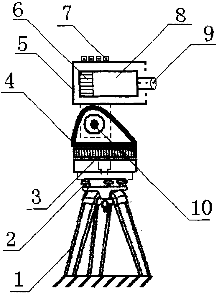
[0024] figure 1 Middle: The laser emitter consists of a fixed bracket 4, a housing 5, a control and power supply unit 6, an operation keyboard 7, a laser 8, a lens 9, and a stepping motor 10; 3 on the bracket 1.

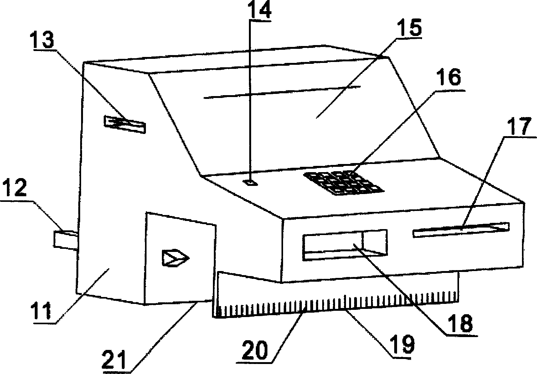
[0025] figure 2 Middle: housing 11, rail positioning pin 12, IC card storage port 13, power switch 14, LCD display 15, operating keyboard 16, light detection slot 17, light positioning display 18, positioning scale 19, capacitance scale 20 , The guide rail groove 21 forms a laser detector and a microprocessor control system.

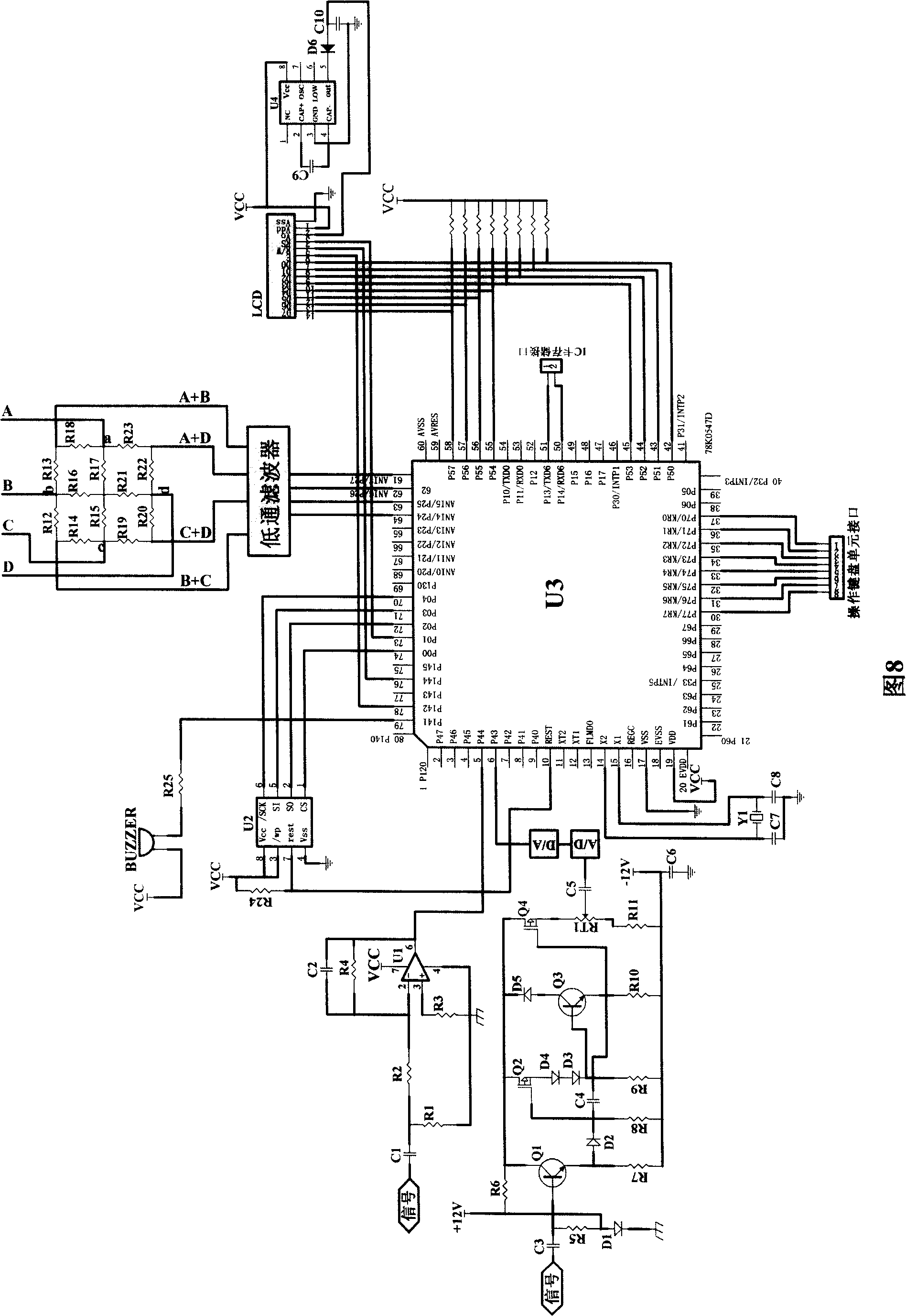
[0026] image 3 Middle: The microprocessor control system includes a microprocessor, a laser detector, a constant temperature unit, a capacitive scale, a stepping motor, a display unit, a storage unit, and a key unit. The constant temperature unit is composed of a cooling crystal and a fan.

[0027] Figure 4 Middle: The traditional subgrade test platform is composed of rail beams 22, tracks 23, reference points 24, test platforms 25, an...


PUM


Abstract

The present invention provides a method of adopting a laser measurement technique to measure the longitudinal displacement of railway tracks, which mainly relates to the measurement of railway maintenance departments for the longitudinal displacement of tracks. A corresponding control strategy is utilized through a micro programming controller for figuring out the track displacement offset after a control system receives a light source emitted by a laser emitter through a laser detector. The method overcomes the characteristics that the prior measurement equipment is great in centering and collimation difficulty, troublesome to adjust and susceptible to human and environmental factors, and the like, adopts laser collimation properties, utilizes the laser detector, capacitive-gate ruler positioning and other measurement modes, automatically acquires data signals through the embedded control strategy and calculation methods of a micro-processing controller, works out the longitudinal offset displacement of the tracks. The method has the advantages of simple operation, convenient detection, visual clear display, high measurement precision and the like.

Description

technical field [0001] The invention relates to the measurement of the longitudinal displacement of the rail by the railway engineering department, and mainly adopts the laser measurement technology to realize the method for measuring the longitudinal displacement of the railway rail. Background technique [0002] With the continuous improvement of the national economy, in order to meet the needs of the transportation market and improve the competitiveness of railway transportation in the transportation market, railway transportation is constantly developing in the direction of high speed and heavy load. However, my country's railway lines are developed under the condition of mixed loads of passengers and goods. Due to the inherent characteristics of seamless lines, their daily maintenance is quite different from that of ordinary lines. The railway engineering department must accurately handle various basic technical parameters in order to ensure the safety of the line. [...

Claims


Application Information

Patent Timeline
Patent Type & Authority Patents(China)
IPC IPC(8): G01B11/02
Inventor 宫春勇高小群赵华
Owner SHANDONG SHENPU TRAFFIC TECHNOLOGY CO LTD
Learn More