
A two-phase flow split-phase holdup conductivity sensor and its structure parameter optimization method

A sensor and conductance technology, which is applied in the field of two-phase flow split-phase holdup conductance sensor and its structural parameter optimization, can solve the problems of uneven solid phase distribution of the sensor, limited measurement range and accuracy, and rapid flow pattern change, etc. Achieve the effect of rapid optimization of structural parameters, widened measurement range, and avoidance of floating

Inactive Publication Date: 2012-02-22
TIANJIN UNIV
View PDF0 Cites 0 Cited by
  • Summary
  • Abstract
  • Description
  • Claims
  • Application Information

AI Technical Summary

Problems solved by technology

However, the two-phase flow process is very complicated, the solid phase distribution in the sensor is uneven, and the flow pattern changes rapidly; at the same time, because the detection field of the electrical sensor is a "soft field", its sensitivity distribution changes with the phase distribution, and its inherent sensitivity distribution Inhomogeneity will lead to measurement results not only related to phase concentration, but also its measurement accuracy is affected by phase distribution and flow pattern changes
[0003] At present, the electrode array of the two-phase flow separation phase holdup conductivity sensor designed for industrial applications is generally in contact with the measured substance. The electrodes are floating, which can easily lead to saturation of the resistance / conductance measurement circuit, limiting its measurement range and accuracy

Method used


Image

  • A two-phase flow split-phase holdup conductivity sensor and its structure parameter optimization method
  • A two-phase flow split-phase holdup conductivity sensor and its structure parameter optimization method
  • A two-phase flow split-phase holdup conductivity sensor and its structure parameter optimization method

Examples


Embodiment Construction

[0016] A two-phase flow separation phase holdup conductivity sensor and its structural parameter optimization method of the present invention will be described in conjunction with the accompanying drawings and embodiments.

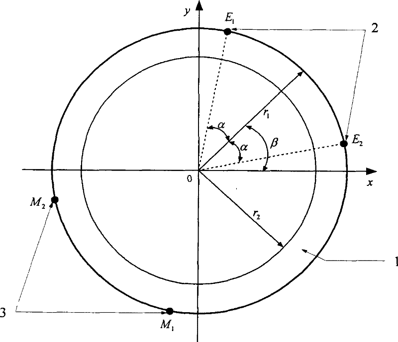
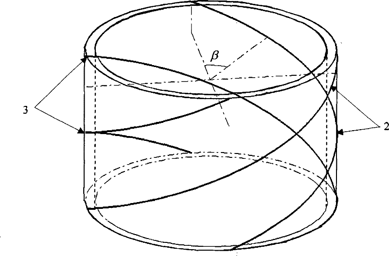
[0017] Such as figure 1 , 2 As shown, the two-phase flow split-phase holdup conductivity sensor of the present invention is connected in series in the pipeline of the two-phase flow, and includes an excitation electrode pair and a measurement electrode pair, and the excitation electrode pair 2 and the measurement electrode pair 3 are attached to On the conductive ring layer 1. The pair of excitation electrodes 2 and the pair of measurement electrodes 3 are arranged radially symmetrically with respect to the conductive ring layer 1, and are spirally distributed at an angle of 180 degrees. figure 1 It shows the cross-section of the structure in the two-phase flow phase holdup conductivity sensor, which is composed of a conductive ring layer 1 and an electr...


PUM

PropertyMeasurementUnit
angleaaaaaaaaaa

Abstract

The invention provides a two-phase flow separation phase holdup conductivity sensor. The sensor is composed of a conductive ring layer and an excitation electrode pair and a measurement electrode pair attached to it. The excitation electrode and the measurement electrode are on the upper diameter of the pipe wall of the conductive ring layer. Symmetrically distributed in a spiral at an angle of 180 degrees. At the same time, a structural parameter optimization method based on the above-mentioned sensor structure is also provided. The beneficial effects of the present invention are aimed at the real-time measurement of the phase holdup of two-phase flow, which overcomes the shortcoming that the measurement electrode is in contact with the non-conductive substance in the traditional conductivity sensor, which causes the measurement electrode to float, and provides a conductivity type electrical sensor based on its analysis The model gives the expression of the sensitivity distribution at any point on the two-dimensional sensor cross-section, which can quickly optimize the structural parameters. Belonging to non-invasive rapid measurement, the measurement range is widened, and the cost is low.

Description

technical field [0001] The invention relates to a detection device, in particular to a two-phase flow split-phase holdup conductivity sensor and a structural parameter optimization method thereof. Background technique [0002] Phase holdup is an important parameter for online real-time measurement of two-phase flow, which is of great significance in industrial production and oil transportation. Because the electrical method has the advantages of non-invasive measurement, fast response, safety and reliability, low cost, easy installation, and durability, it is suitable for industrial online applications. When the fluid composition in the pipeline changes, the corresponding electrical parameters change. Through a set of electrode arrays arranged on the inner or outer wall of the pipeline, the change of the electrical signal caused by the change of the fluid composition is measured. According to the electrical measurement between the measuring plates value, the phase concentra...

Claims


Application Information

Patent Timeline
Patent Type & Authority Patents(China)
IPC IPC(8): G01N27/08
Inventor 王化祥曹章
Owner TIANJIN UNIV
Learn More