Complex indoor scene rapid drafting method based on view rejection

An indoor scene and field of view technology, applied in 3D image processing, image data processing, instruments, etc., can solve the problems of high complexity, high occlusion, unrealistic, inefficient tree structure, etc., and achieve The effect of improving memory utilization and improving efficiency

Inactive Publication Date: 2009-04-29
SHANGHAI UNIV
View PDF0 Cites 22 Cited by
  • Summary
  • Abstract
  • Description
  • Claims
  • Application Information

AI Technical Summary

Problems solved by technology

Due to the complexity of indoor scenes, it is definitely unrealistic to use LOD, because they are all close-range models, and image-based rendering algorithms cannot fundamentally solve the requirements for accelerated rendering. Generally, for such indoor environments, they are created using Tree structure, but the tree structure is quite inefficient, because the o

Method used


Image

  • Complex indoor scene rapid drafting method based on view rejection
  • Complex indoor scene rapid drafting method based on view rejection
  • Complex indoor scene rapid drafting method based on view rejection

Examples


Example Embodiment

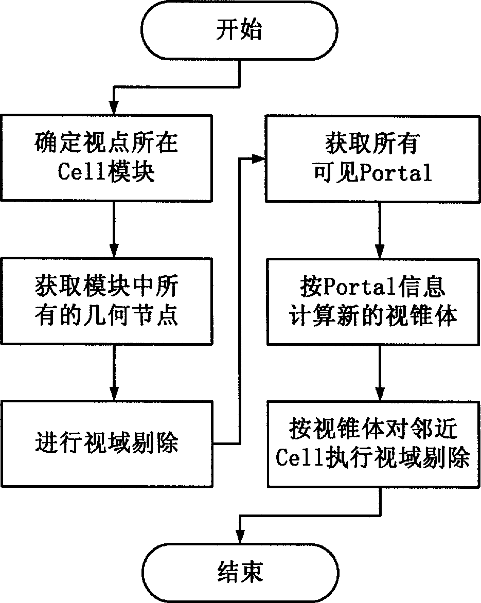
[0023] A preferred embodiment of the present invention is described with reference to the accompanying drawings as follows: The method for quickly drawing a complex indoor scene consists of five steps:

[0024] Step 1: Divide the entire scene into n regions

[0025] Such as figure 1 As shown, in the concept of entry technology, the entire scene is divided into n regions (cells), each region is a closed convex polygon, where “convex” means that a line segment is drawn between any two points in the region. The line segment will not penetrate any polygon in the area, and closed means that a light is emitted from the area. If the light is to be shot outside the area, the light must penetrate a polygon in a certain area. So you can vividly put a The area is regarded as a room, and the polygons of the area constitute the walls, ceiling and floor of the room. (If you want to describe a "convex" room, you need to divide the room into several "convex" areas, and then connect them with the...


PUM


Abstract

The invention relates to a rapid rendering method for a complex indoor scene based on view frustum culling. The method comprises the following steps: firstly, dividing the whole scene into n areas, connecting the adjacent areas by portals, and then determining the position of a view point, performing intersection detection on all geometric modules in an area module and a viewing pyramid, completing the view frustum culling work, and finally computing number of the Portals within a viewable scope, computing a new viewing pyramid, performing the new view frustum culling, and recursing the steps to obtain a node that needs rendering. Experimental results prove that the rendering efficiency can be greatly improved by the indoor scene management method provided by the invention when the indoor shielding rate is high.

Description

technical field [0001] The invention relates to graphics processing and virtual reality, and mainly relates to a fast drawing method of a scene graphics engine, in particular to a fast drawing method of a graphics engine based on an indoor scene graph structure. Background technique [0002] Due to the increasingly complex scenes drawn by computers, in order to achieve real-time effects, the requirements for computer software and hardware will only become higher and higher. It requires the use of advanced rendering algorithms to plan and manage complex scenes and optimize scene management algorithms. , to speed up the speed of drawing scenes, usually the graphics quality is directly proportional to the amount of calculation, the greater the amount of calculation, the better the quality of the graphics, but considering the real-time requirements in virtual reality, it is necessary to balance the two Consider, while satisfying the visual effect, speed up the drawing as much as...

Claims


Application Information

Patent Timeline
IPC IPC(8): G06T15/20
Inventor 余小清万旺根周俊玮丁欢
Owner SHANGHAI UNIV
Why Eureka
Try Eureka