Heat radiating device for LED and manufacturing method therefor

A technology of light-emitting diodes and heat sinks, which is applied to the cooling/heating devices of lighting devices, lighting devices, semiconductor devices of light-emitting elements, etc., and can solve the problem of insufficient flat surface area, unequal lifespan of light-emitting diodes, and poor contact between light-emitting diodes and heat pipe surfaces Close and other issues

Inactive Publication Date: 2009-04-29
FU ZHUN PRECISION IND SHENZHEN +1
View PDF0 Cites 1 Cited by
  • Summary
  • Abstract
  • Description
  • Claims
  • Application Information

AI Technical Summary

Problems solved by technology

[0002] Light Emitting Diode (LED) lamps are being widely used due to their advantages of energy saving and environmental protection. However, high-brightness and high-power LEDs generate a lot of heat. As a result, the luminous efficiency is significantly reduced, and even the components are damaged. The industry usually installs a radiator under the LED lamp to dissipate heat, and what is more, a heat pipe is embedded at the bottom of the radiator, and then the LED is attached to the The surface of the heat pipe is expected to improve the heat dissipation efficiency through the high thermal conductivity of the heat pipe
However, the surface of the heat pipe is often not smooth enough and the surface area is small, resulting in a part of the light-emitting diodes not in close contact with the surface of the heat pipe, forming a gap between the light-emitting diodes and the surface of the heat pipe to affect heat conduction, thus causing the temperature of the local light-emitting diodes to be too high or even damaged. LEDs in the same luminaire have different lifetimes, which affect the performance of the luminaire

Method used


Image

  • Heat radiating device for LED and manufacturing method therefor
  • Heat radiating device for LED and manufacturing method therefor
  • Heat radiating device for LED and manufacturing method therefor

Examples


Embodiment Construction

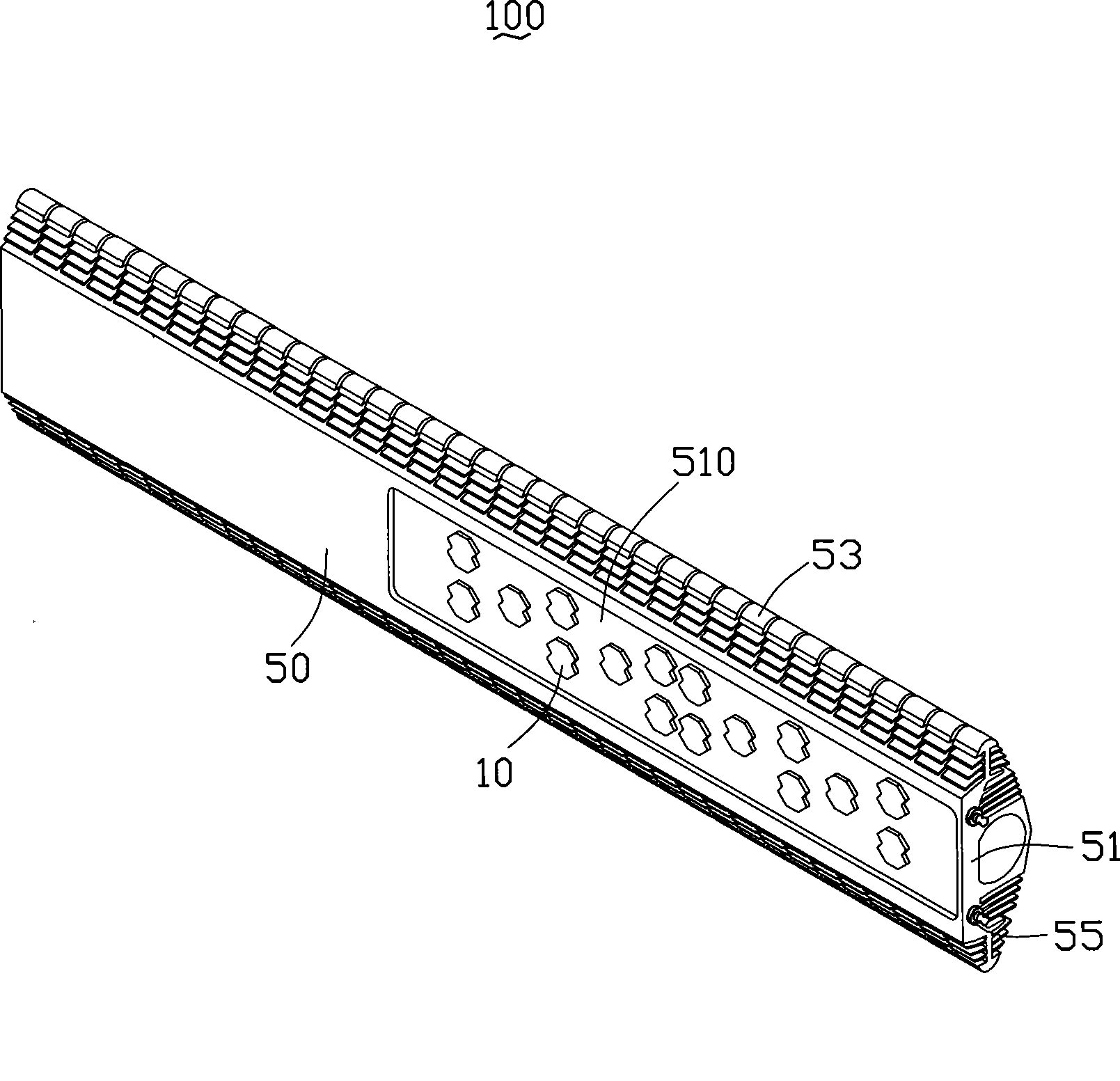
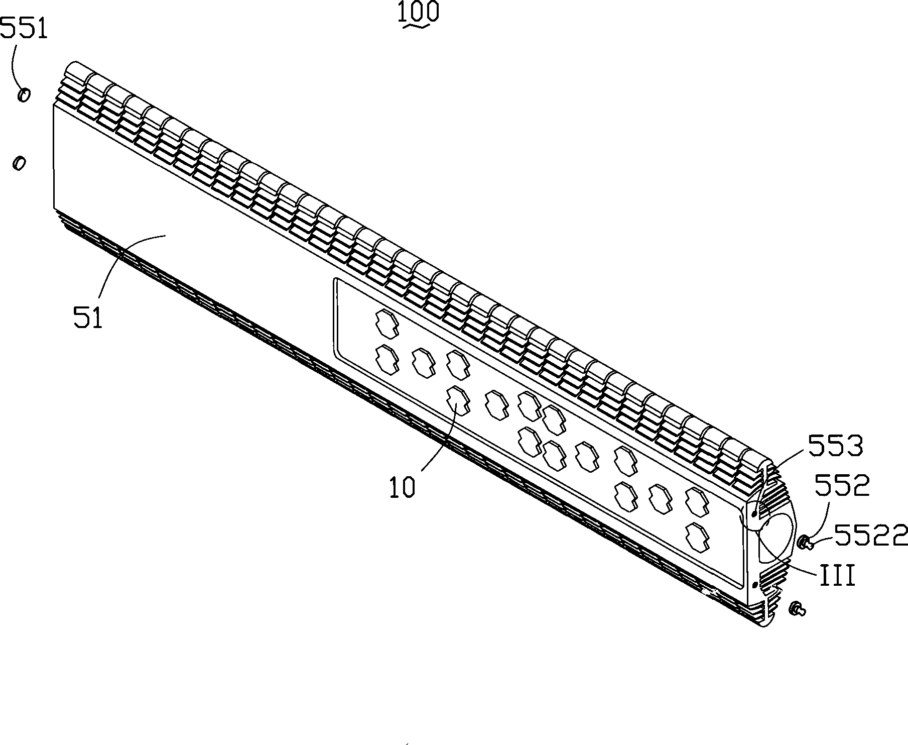
[0010] see figure 1 and figure 2 , is an LED lamp 100 according to an embodiment of the present invention. The lamp 100 includes a heat sink 50 and a plurality of LEDs 10 attached to the bottom of the heat sink 50 .

[0011] The heat dissipation device 50 includes a base plate 51 and a plurality of heat dissipation fins 53, and these heat dissipation fins 53 extend from the top surface and sides of the base plate 51 to expand the contact area between the heat dissipation device 50 and the surrounding air and improve heat dissipation. efficiency.

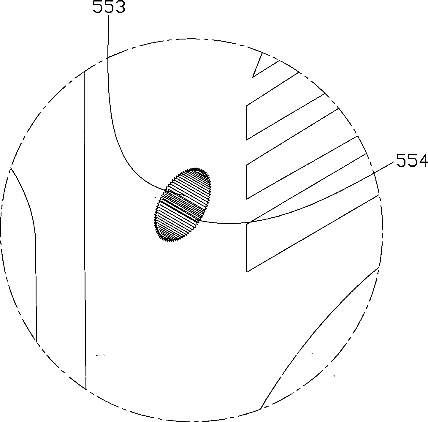
[0012] The substrate 51 is roughly in the shape of a rectangular plate with a certain thickness. A notch 510 is provided on the right side of the bottom of the substrate 51. The LEDs 10 are attached to the bottom surface of the notch 510. A The lampshade (not shown) snapped on the edge of the notch 510 . Please also see image 3 , the substrate 51 includes two channels 553 disposed at the bottom thereof and adjacent to the LEDs ...


PUM


Abstract

An LED heat sink comprises a substrate and a plurality of LEDs which are pressed at the bottom of the substrate. At least one heat tube structure is formed in the substrate and integrated with the substrate as a whole; each heat tube structure comprises a channel which is arranged in a base, a capillary structure and working fluid are arranged inside the channel, and the two ends of the channel are respectively sealed. The invention further discloses a manufacturing method of the LED heat sink. The bottom surface of the substrate has relatively flat forming and large surface area, and the LEDs can keep close contact with the bottom surface, thus ensuring the effectiveness and the evenness of heat transfer between the LEDs and the substrate and causing the service life of various LEDs to be kept basically the same; meanwhile, the substrate is provided with the heat tube structure which can ensure that the heat sink has higher heat conduction efficiency.

Description

technical field [0001] The invention relates to a light-emitting diode cooling device, in particular to a cooling device with a heat pipe and a manufacturing method thereof. Background technique [0002] Light Emitting Diode (LED) lamps are being widely used due to their advantages of energy saving and environmental protection. However, high-brightness and high-power LEDs generate a lot of heat. As a result, the luminous efficiency is significantly reduced, and even the components are damaged. The industry usually installs a radiator under the LED lamp to dissipate heat, and what is more, a heat pipe is embedded at the bottom of the radiator, and then the LED is attached to the The surface of the heat pipe is expected to improve the heat dissipation efficiency through the high thermal conductivity of the heat pipe. However, the surface of the heat pipe is often not smooth enough and the surface area is small, resulting in a part of the light-emitting diodes not in close con...

Claims


Application Information

Patent Timeline
Patent Type & Authority Applications(China)
IPC IPC(8): H01L25/00H01L25/075H01L23/427H01L21/50
CPCF21K9/00F21V29/006H01L2924/0002F21V29/75F21V29/76F21Y2115/10H01L2924/00
Inventor 余方祥詹顺渊黄中元
Owner FU ZHUN PRECISION IND SHENZHEN
Why Eureka
Try Eureka