Video light machine for implementing circuit break alarm

An optical transceiver and video technology, which is applied in the field of video optical transceivers, can solve the problems of inconvenient maintenance, inability to know whether the transmitter is powered off or not, and does not have a power off alarm function, etc., and achieves the effect of great convenience and high cost performance.

Inactive Publication Date: 2009-04-29
武汉众智数字技术有限公司
View PDF0 Cites 2 Cited by
  • Summary
  • Abstract
  • Description
  • Claims
  • Application Information

AI Technical Summary

Problems solved by technology

With the increase in the deployment of video optical transceivers, the amount of maintenance at the transmitting end is also increasing. However

Method used


Image

  • Video light machine for implementing circuit break alarm
  • Video light machine for implementing circuit break alarm
  • Video light machine for implementing circuit break alarm

Examples


Embodiment Construction

[0037] Below in conjunction with accompanying drawing and implementation the present invention is further described:

[0038] 1. Overall

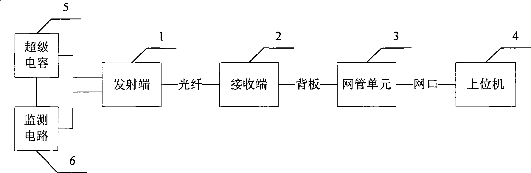
[0039] Such as figure 1 , 2 , the video optical transceiver includes the existing video optical transceiver, that is, it includes the transmitting terminal 1, the receiving terminal 2, the network management unit 3 and the host computer 4 connected in sequence;

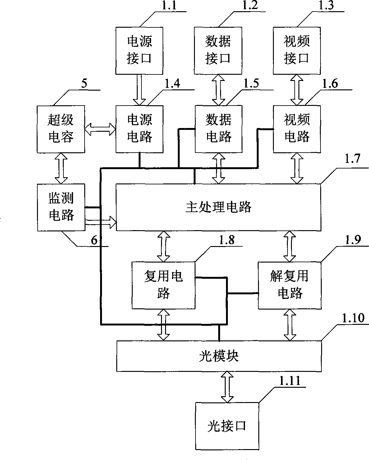
[0040] The main structure of the transmitter 1 is:

[0041] Video interface 1.3, video circuit 1.6 and main processing circuit 1.7 are connected sequentially;

[0042] The data interface 1.2, the data circuit 1.5 and the main processing circuit 1.7 are sequentially connected;

[0043] Main processing circuit 1.7, multiplexing circuit 1.8, optical module 1.10 and optical interface 1.11 are connected in sequence;

[0044] Optical interface 1.11, optical module 1.10, demultiplexing circuit 1.9 and main processing circuit 1.7 are connected in sequence;

[0045] The power supply i...


PUM


Abstract

The present invention relating to a video optical transmitter and receiver discloses a video optical transmitter and receiver capable of giving a power-off alarm. The present invention comprises an existing video optical transmitter and receiver, namely, comprises a transmitting terminal (1), a receiving terminal (2), network management unit (3) and a host computer (4) which are connected in order; a super capacitor (5) and an observation circuit (6) are also provided, and a power supply circuit (1.4), the super capacitor (5), the observation circuit (6) and a main processing circuit (1.7) are connected in order. The super capacitor (5) is a Farad capacitor with 1 farad capacitance, and the maximum working voltage is 5.5V; a main device of the observation circuit (6) adopts a single-chip microcontroller P89LPC935. According to the present invention, a transmitter power-off alarm can be reported to a network management center correctly, therefore the video optical transmitter and receiver has the characteristics of great convenience for using and maintaining, small increase of cost for the power-off alarm function and high cost performance.

Description

technical field [0001] The invention relates to a video optical transceiver, in particular to a video optical transceiver capable of realizing power failure alarm. Background technique [0002] Video optical transceivers are generally deployed centrally at the receiving end and distributed at the transmitting end. During maintenance, since the receiving end is deployed in a centralized manner, for example, it is all deployed in the central computer room, so it only needs to be maintained in one place, and the workload is relatively small. However, the transmitters are distributed and deployed in different places, such as various intersections, and maintenance needs to be carried out at each deployment point, and the workload is very huge. With the continuous advancement of security projects such as "Safe City", the demand for video optical transceivers has also shown a blowout development. With the increase in the deployment of video optical transceivers, the amount of mai...

Claims


Application Information

Patent Timeline
IPC IPC(8): H04B10/12H04B10/14H04N5/38H04B10/40
Inventor 李华民谷浩刘杰陈军旗
Owner 武汉众智数字技术有限公司
Why Eureka
Try Eureka