Electronic device cooling system and electronic device cooling apparatus

A technology for electronic equipment and cooling systems, which is applied in the field of electronic equipment cooling systems and electronic equipment cooling devices, can solve the problems of increasing the number of parts, and achieve the effects of reducing energy consumption and suppressing deflection

Inactive Publication Date: 2009-04-29
SANYO ELECTRIC CO LTD
View PDF2 Cites 26 Cited by
  • Summary
  • Abstract
  • Description
  • Claims
  • Application Information

AI Technical Summary

Problems solved by technology

However, the conventional cooling device for electronic equipment has increased the number of parts due to the installation of a heater for humidity control and a moisture absorbing and dehumidifying element.
In addition, existing devices require strict protection against water leakage due to the use of cooling water near electronic equipment.

Method used


Image

  • Electronic device cooling system and electronic device cooling apparatus
  • Electronic device cooling system and electronic device cooling apparatus
  • Electronic device cooling system and electronic device cooling apparatus

Examples


Embodiment Construction

[0063] Hereinafter, embodiments of the present invention will be described in detail with reference to the drawings.

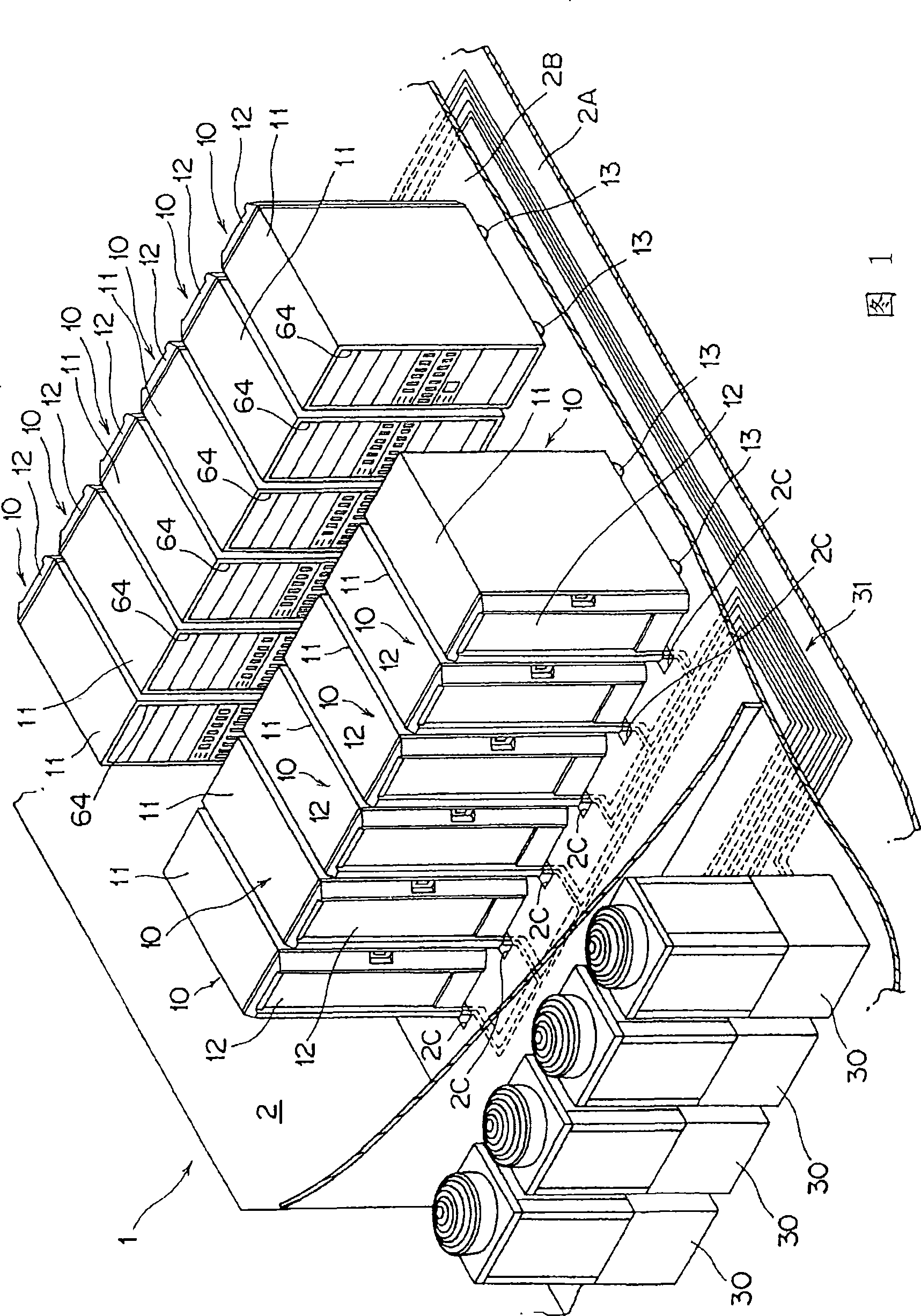
[0064] FIG. 1 is a diagram showing an electronic device cooling system according to an embodiment of the present invention.

[0065] This electronic equipment cooling system 1 is to arrange a plurality of electronic equipment 3 in the computer room 2 (refer to figure 2 ) cooling system. The computer room 2 is configured with double decks, and a server cabinet (subarak) 10 is placed on the double decks.

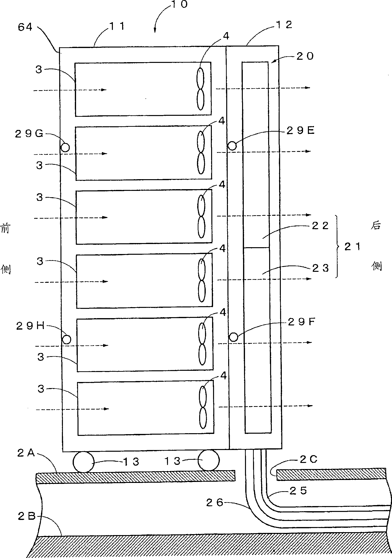
[0066] figure 2 is a diagram showing the server rack 10 . The server rack 10 has a box body 11 with front and rear openings, and in the box body 11 , a plurality of electronic devices 3 are stacked up and down with their backs facing the back of the box body 11 . In addition, a single-leaf rear door 12 capable of closing the rear opening 65 is provided at the rear of the housing 11, and the rear door 12 is configured to be ventilated freely, and an electro...


PUM


Abstract

An electronic cooling apparatus has a cabinet which is opened at the front and rear sides thereof and accommodates plural electronic devices each having a fan, and a rear door which is provided with an evaporator. Air blown by the fan is cooled by the evaporator and then returned to a room. An expansion valve and an electronic component unit for controlling the expansion valve are provided integrally with the evaporator. A drain pan for receiving drain water dropping from the evaporator is provided at the lower side of the evaporator. Furthermore, an exhaust temperature detecting unit for detecting exhaust heat temperature of the electronic device and a controller for controlling the refrigerant supply to the evaporator are provided. When the exhaust heat temperature is equal to or less than a set exhaust temperature which is defined in a computer room so that no dew condensation occurs in the evaporator, the controller stops the refrigerant supply to the evaporator, and when the exhaust heat temperature exceeds the set exhaust heat temperature, the controller starts the refrigerant supply to the evaporator.

Description

technical field [0001] The present invention relates to an electronic equipment cooling system and an electronic equipment cooling device that cool air blown by a fan attached to an electronic equipment housed in a housing. Background technique [0002] Generally, an electronic equipment cooling system (for example, US Patent Application Publication No. 2006 / 0232945 specification) and an electronic equipment cooling device (Japanese Patent Application Laid-Open No. 8-316676 ) having the following structures are known, and the electronic equipment cooling system is used to house electronic equipment The air outlet side of the box is equipped with an air-water heat exchanger, and the air blown by the fan is cooled by the above-mentioned air-water heat exchanger and then returned to the room. The fan is attached to the electronic equipment housed in the box. superior. [0003] This electronic equipment cooling system is installed in a computer room, and cools servers or networ...

Claims


Application Information

Patent Timeline
Patent Type & Authority Applications(China)
IPC IPC(8): H05K7/20F25D9/00F25B1/00
Inventor 栗山博之野村和雄镜一丰齐藤顺一关根卓永江公二西野重孝
Owner SANYO ELECTRIC CO LTD
Why Eureka
Try Eureka