
Sealing system with pressure relief elements and use of a sealing system for producing a pressure cascade in an intermediate space

A technology of sealing system and decompression components, applied in the direction of engine sealing, engine components, mechanical equipment, etc., can solve the problems of component damage, total system failure, component rupture, etc.

Active Publication Date: 2009-04-29
TRELLEBORG SEALING SOLUTIONS GERMANY
View PDF1 Cites 6 Cited by
  • Summary
  • Abstract
  • Description
  • Claims
  • Application Information

AI Technical Summary

Problems solved by technology

A buildup of such pressure can lead to failure of the component up to rupture of the component and failure of the total system

Method used


Image

  • Sealing system with pressure relief elements and use of a sealing system for producing a pressure cascade in an intermediate space
  • Sealing system with pressure relief elements and use of a sealing system for producing a pressure cascade in an intermediate space
  • Sealing system with pressure relief elements and use of a sealing system for producing a pressure cascade in an intermediate space

Examples


Embodiment Construction

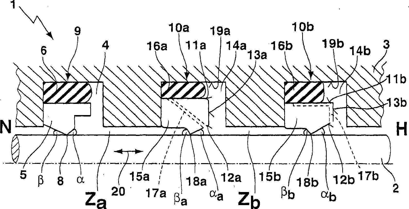
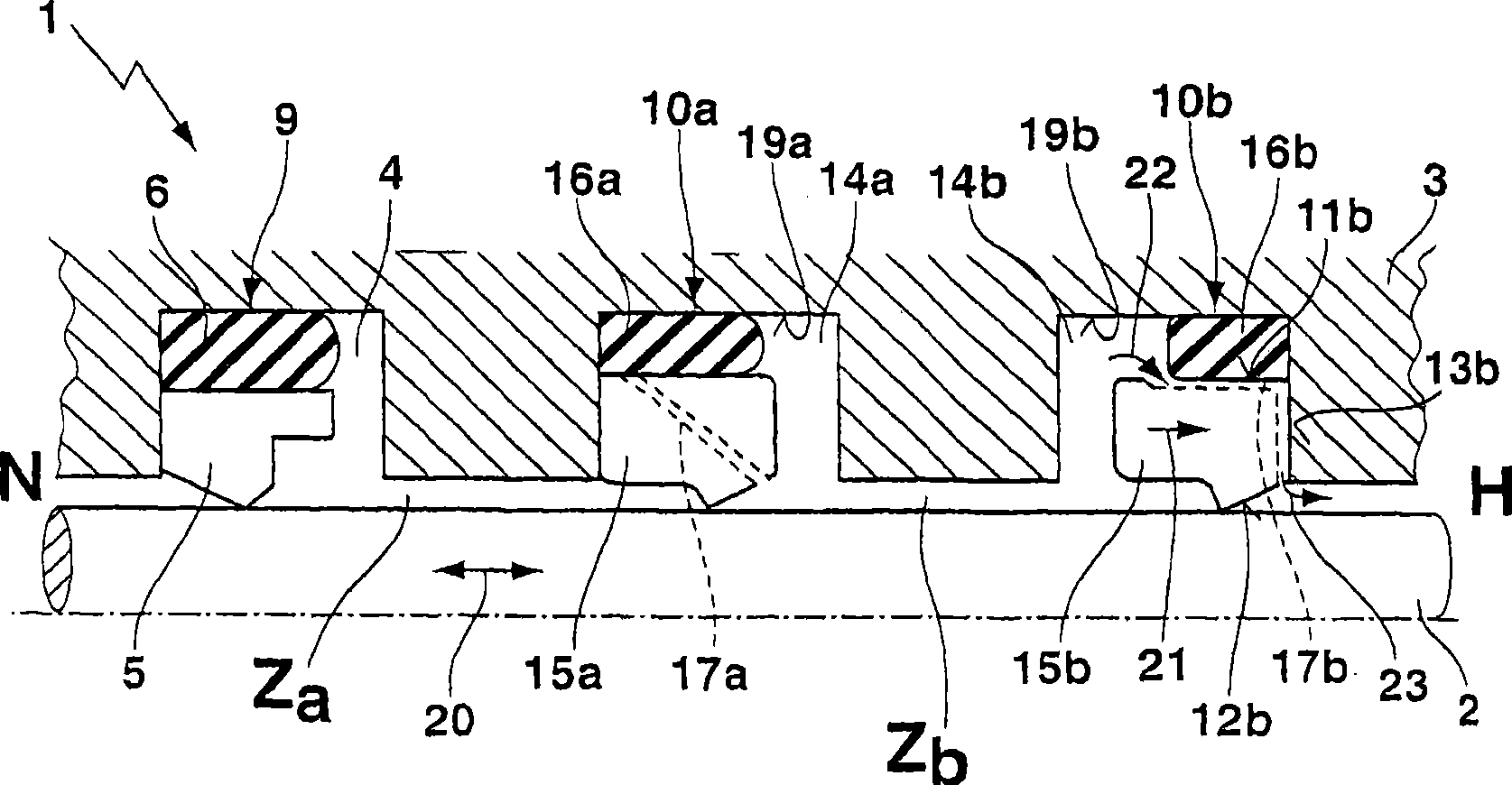
[0051] figure 1 A sealing system according to the invention between two components movable relative to one another is shown for sealing a high-pressure side H relative to a low-pressure side N. FIG. An inner component 2 is arranged within an outer component 3 such that it can perform a translational movement in the axial direction. The outer part 3 is a cylindrical housing and the inner part 2 is the piston rod of a piston guided in the housing. An interchange of the inner part 2 and the outer part 3 is conceivable, for example an embodiment in which the outer part 3 is a piston and the inner part 2 is a tube. figure 1 A longitudinal section view of the upper half space of the sealing system is shown in .

[0052] The outer component 3 has a total of three annular grooves open to the inner component 2 , a first annular groove 4 facing the low-pressure side N and two second annular grooves 14 a and 14 b arranged on the high-pressure side H. A sealing device 9 is arranged i...


PUM


Abstract

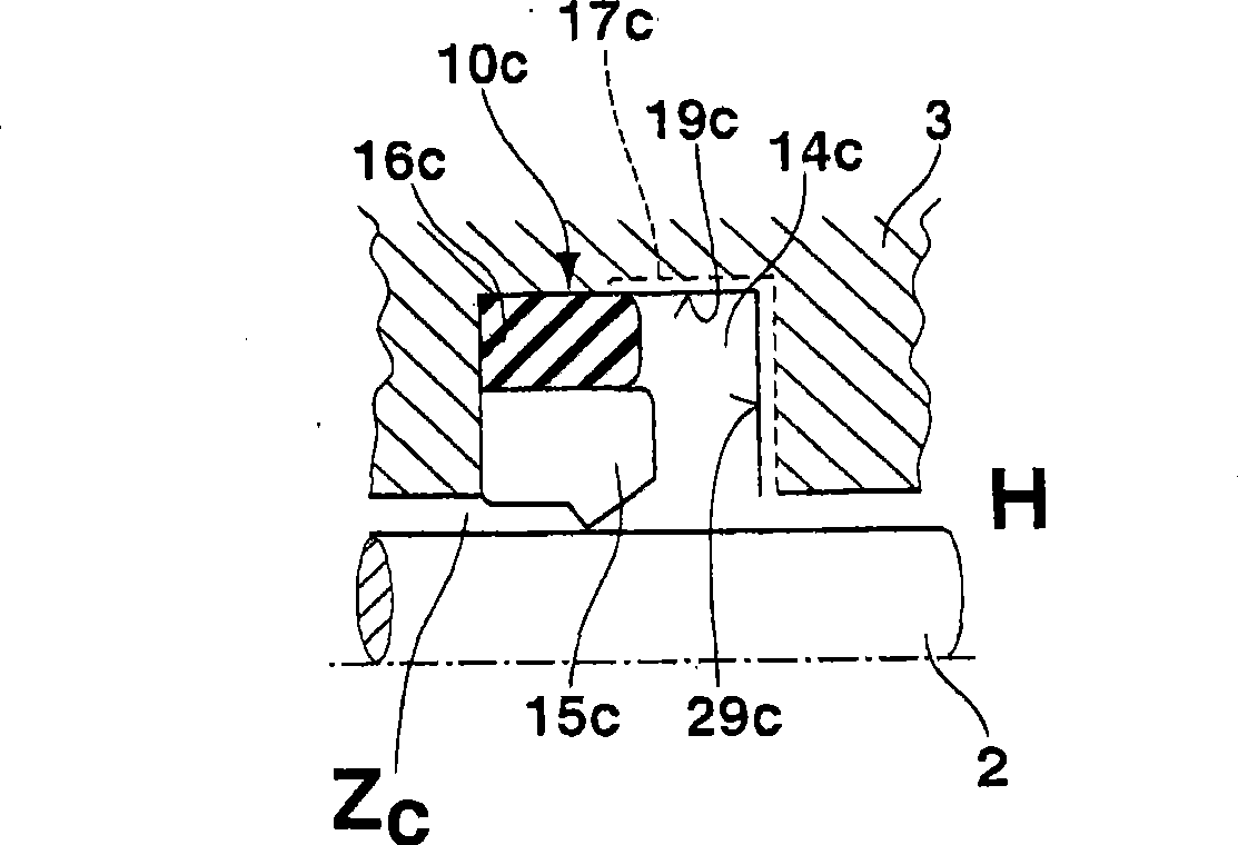
The invention relates to a sealing system (1) between two components (2, 3) that can move relative to one another for sealing a high-pressure side (H) against a low-pressure side (N). In a sealing arrangement (9) provided in a first annular groove (4), one or more pressure relief elements (10a, 10b) are arranged upstream at the high-pressure side in second annular grooves (14a, 14b). The pressure relief elements (10a, 10b) each comprise a second sealing ring (15a, 15b) with flat pressure gradients. The hydrodynamic leakage rate for each pressure relief element (10a, 10b) is selected such that a certain hydraulic pressure prevails in each intermediate space (Za, Zb), thus resulting in a pressure cascade in the intermediate space.; The sealing system (1), according to the invention, comprises, in addition to the hydrodynamic feed capabilities of the sealing rings (5, 15a, 15b), a hydrostatic relief facility via connecting channels (17a, 17b) provided in the pressure relief elements (10a, 10b), said connecting channels acting as non-return valves and generating a pressure relief of an intermediate space (Zb) when the pressure of the intermediate space is increased above the pressure of the following intermediate space at the high-pressure side plus a corresponding pressure increase variable.

Description

technical field [0001] The invention relates to a sealing system for sealing a high-pressure side relative to a low-pressure side between two components which are movable relative to one another. An outer component has a first annular groove open to an inner component facing the low pressure side for accommodating a sealing device and a second annular groove open to the inner component facing the high pressure side for receiving a pressure relief element. The sealing device includes a first sealing ring made of elastically deformable material and a first biasing ring made of elastically deformable material. The first sealing ring bears against the inner component and is clamped radially by the first biasing ring, which additionally seals against the first annular groove. Background technique [0002] In such a sealing system, a medium pressure can build up in the gap between the elements arranged in the respective annular groove in the operating state, ie in the case of a t...

Claims


Application Information

Patent Timeline
Patent Type & Authority Applications(China)
IPC IPC(8): F16J15/16F16J15/56
CPCF16J15/164
Inventor H·约尔丹
Owner TRELLEBORG SEALING SOLUTIONS GERMANY
Learn More