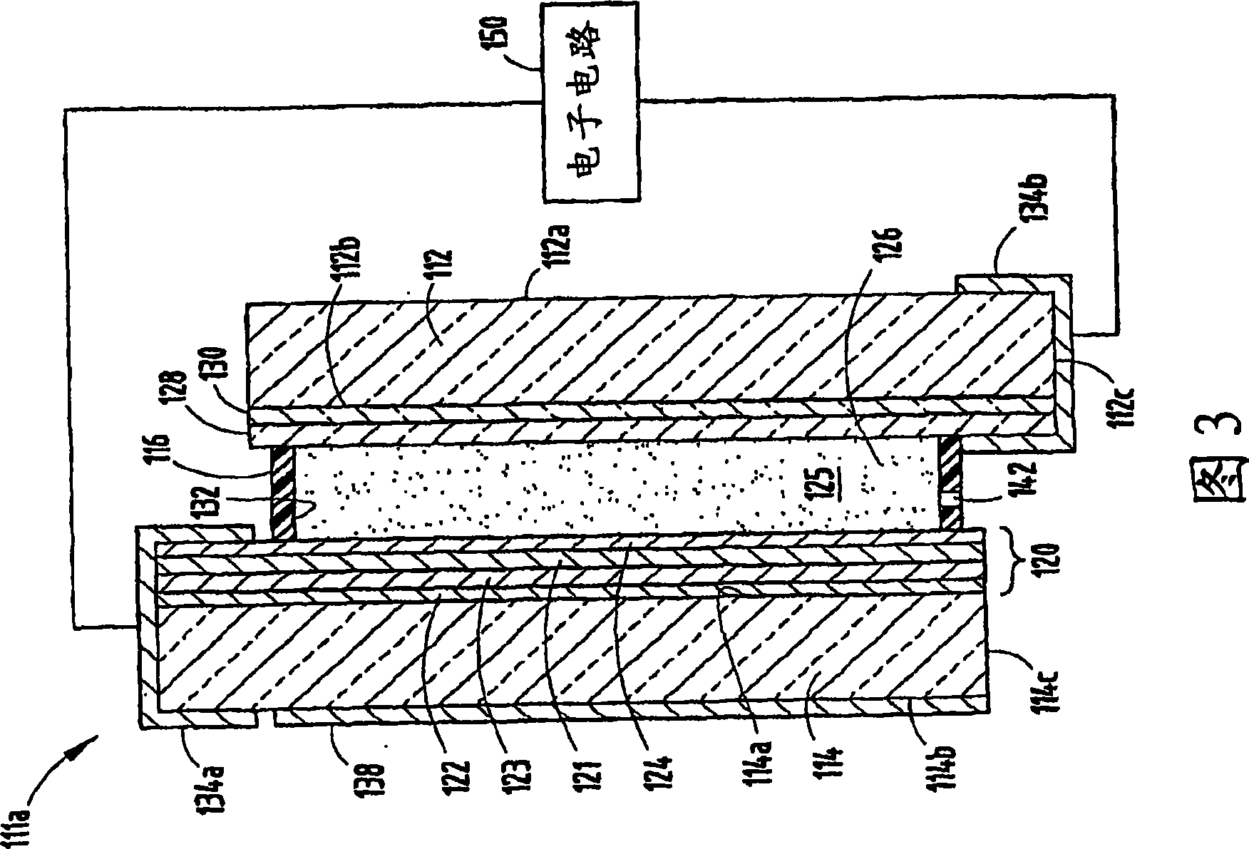
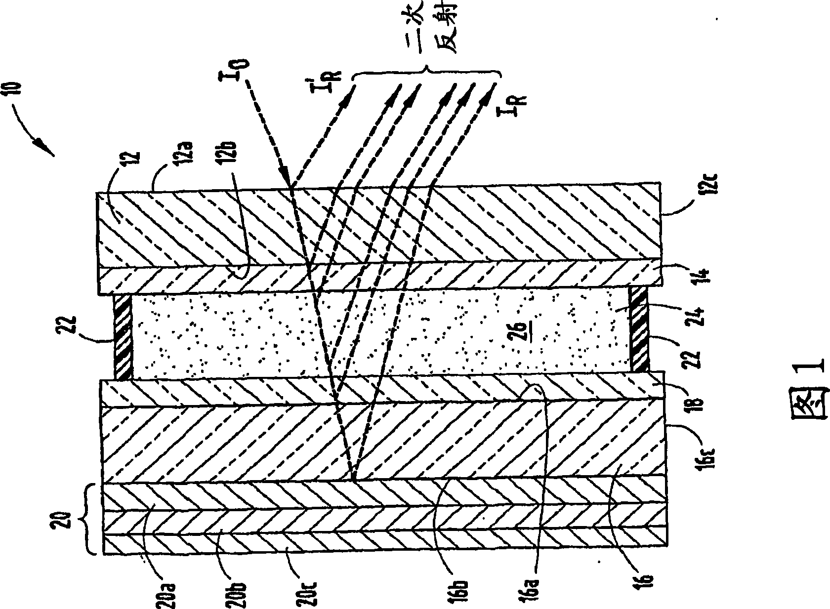
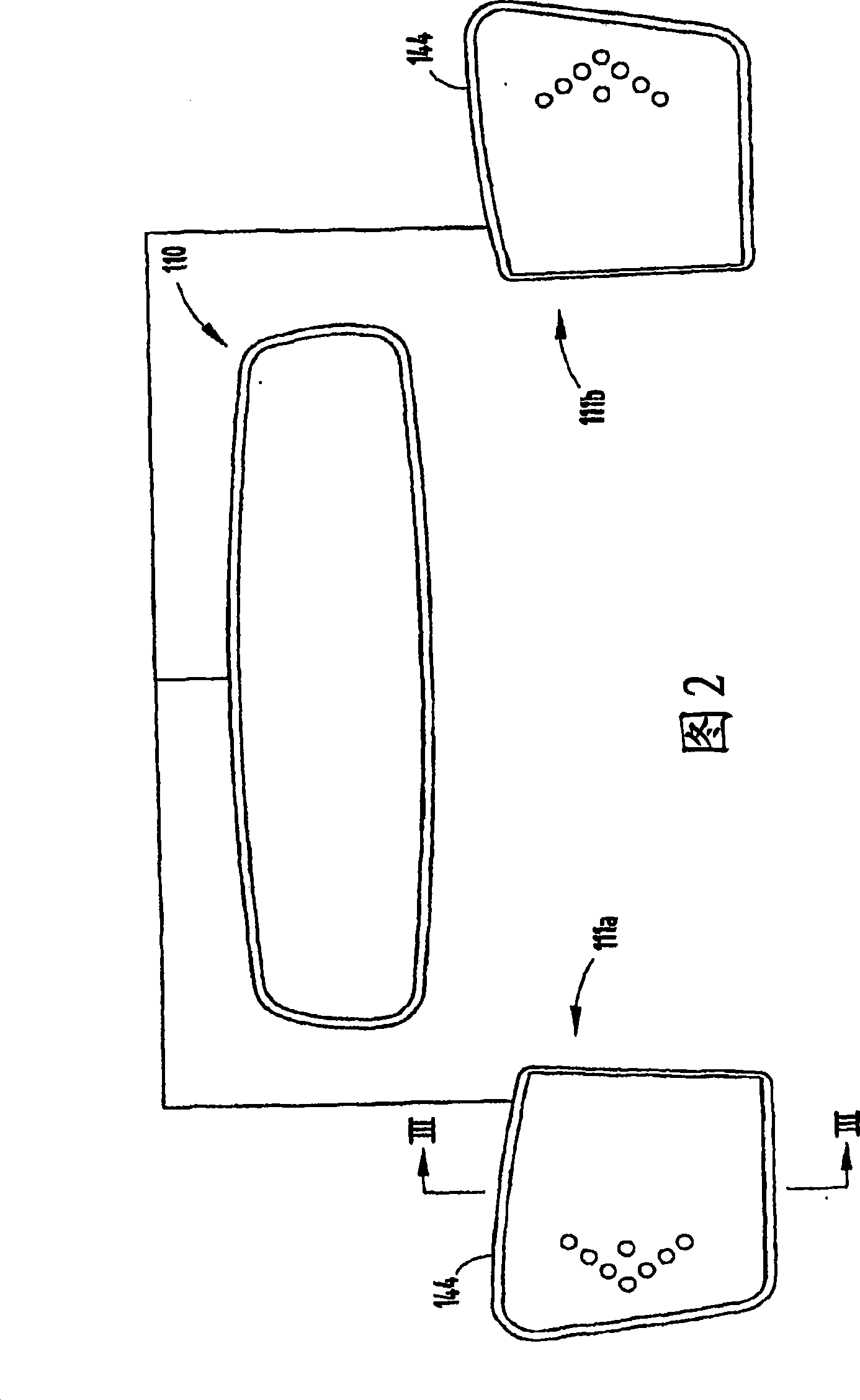
Electro-optical element including metallic films and methods for applying the same
A component, organometallic technology for improved electrochromic components that is time consuming, expensive to recycle, not efficient
- Summary
- Abstract
- Description
- Claims
- Application Information
AI Technical Summary
Problems solved by technology
Method used
Image

Examples
example 1
[0072] Inkjet Silver ConductorAG-IJ-G-100-S1 ink from Cabot Printable Electronics and Displays (Albuquerque, NM) was applied using a JetDrive III driver and MJ-AB-01 40 μm inkjet head obtained from MicroFab Technologies (Plano, TX). Cladding to flat, 1.6 mm thick soda lime glass. Printing parameter settings are typical for inkjet printing. After printing the conductive ink, the isolated samples were cured in a convection oven or drying oven at temperatures of 200, 300, 400 and 500° C. for 20 minutes. The thickness of the cured film was measured using a profilometer (Dektek) and the volume resistivity was calculated.
[0073]
Curing temperature (°C)
Curing time (min) Thickness (μm)
(avg.of 3) Volume resistivity (μΩ·cm)
(avg.of 3) 200 20 0.87 10.63 300 20 1.06 4.24 400 20 0.86 2.90 500 20 1.00 3.11
[0074] Adhesion between films and substrates was evaluated by tape peel test. After curing, an adhesive tape is applie...
example 2
[0077] Silverjet DGH 50LT-25CIA ink from AdvancedNano Products (Seoul, Korea) was applied to flat, 1.6 mm thick soda lime glass using equipment and printing parameter settings similar to Example 1 . After printing the conductive ink, the isolated samples were cured in a convection oven or drying oven at temperatures of 250, 350, 450 and 560° C. for 20 minutes. The thickness of the cured film was measured using a profilometer (Dektek) and the volume resistivity was calculated.
[0078] Curing temperature (°C)
Curing time (min)
Thickness (μm)
(avg.of 3) Volume resistivity (μΩ·cm)
(avg.of 3) 250 20 3.45 11.64 350 20 3.06 10.69 450 20 2.50 9.65 560 20 1.48 3.34
[0079] Adhesion between films and substrates was evaluated by tape peel test as described in Example 1. A rating of 1 indicates that the film was removed through the tape. A rating of 5 indicates that removal by the tape did not affect the film. How much of the ...
example 3
[0082]Silverjet DGH 50HT-25CIA ink from AdvancedNano Products (Seoul, Korea) was applied to flat, 1.6 mm thick soda lime glass using equipment and printing parameter settings similar to Example 1 . After printing the conductive ink, the isolated samples were cured in a convection oven or drying oven at temperatures of 250, 350, 450 and 560° C. for 20 minutes. The thickness of the cured film was measured using a profilometer (Dektek) and the volume resistivity was calculated.
[0083]
Curing temperature (°C)
Curing time (min) Thickness (μm)
(avg.of 3) Volume resistivity (μΩ·cm)
(avg.of 3) 250 20 5.38 18.17 350 20 5.29 17.23 450 20 5.31 17.89 560 20 3.28 7.39
[0084] Adhesion between films and substrates was evaluated by tape peel test as described in Example 1. A rating of 1 indicates that the film was removed through the tape. A rating of 5 indicates that removal by the tape did not affect the film. How much of th...
PUM
| Property | Measurement | Unit |
|---|---|---|
| electrical resistivity | aaaaa | aaaaa |
| electrical resistivity | aaaaa | aaaaa |
| electrical resistivity | aaaaa | aaaaa |
Abstract
Description
Claims
Application Information